• The URRST bit in the power and emulation management register (PWREMU_MGMT) is loaded with 0.
Non-FIFO mode: Transmitter holding A character is written to the
register (THR) is empty.transmitter holding register (THR). FIFO mode: Transmitter FIFO is
empty.
• A new character arrives in the receiver FIFO.
• A character is read from the receiver FIFO.(1)
FIFO mode only: No characters have One of the following events: been removed from or input to the
receiver FIFO during the last four character times (see Table 4), and there is at least one character in the receiver FIFO during this time.
FIFO mode: Trigger level reached. If FIFO mode: The FIFO drops below
four character times (see Table 4) the trigger level.(1) pass with no access of the FIFO, the
interrupt is asserted again.
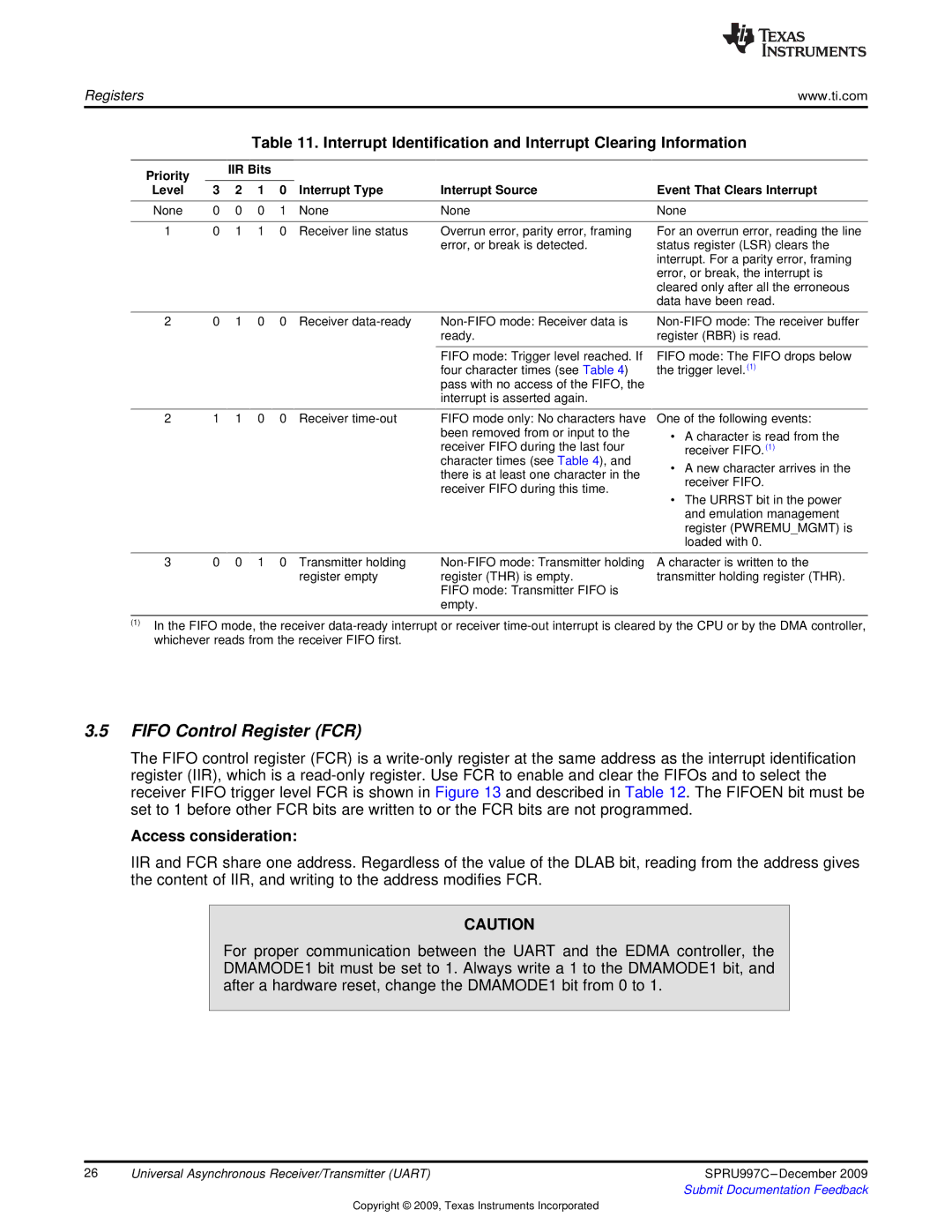
Table 11. Interrupt Identification and Interrupt Clearing Information
Priority | | IIR Bits | | | |
Level | 3 | 2 | 1 | 0 | Interrupt Type | Interrupt Source |
| | | | | | |
None | 0 | 0 | 0 | 1 | None | None |
| | | | | | |
1 | 0 | 1 | 1 | 0 | Receiver line status | Overrun error, parity error, framing |
| | | | | | error, or break is detected. |
2 | 0 1 0 0 Receiver data-ready | Non-FIFO mode: Receiver data is |
| | ready. |
| | |
Event That Clears Interrupt
None
For an overrun error, reading the line status register (LSR) clears the interrupt. For a parity error, framing error, or break, the interrupt is cleared only after all the erroneous data have been read.
Non-FIFO mode: The receiver buffer register (RBR) is read.
2 1 1 0 0 Receiver time-out
3 0 0 1 0 Transmitter holding register empty
(1)In the FIFO mode, the receiver data-ready interrupt or receiver time-out interrupt is cleared by the CPU or by the DMA controller, whichever reads from the receiver FIFO first.
3.5FIFO Control Register (FCR)
The FIFO control register (FCR) is a write-only register at the same address as the interrupt identification register (IIR), which is a read-only register. Use FCR to enable and clear the FIFOs and to select the receiver FIFO trigger level FCR is shown in Figure 13 and described in Table 12. The FIFOEN bit must be set to 1 before other FCR bits are written to or the FCR bits are not programmed.
Access consideration:
IIR and FCR share one address. Regardless of the value of the DLAB bit, reading from the address gives the content of IIR, and writing to the address modifies FCR.
CAUTION
For proper communication between the UART and the EDMA controller, the DMAMODE1 bit must be set to 1. Always write a 1 to the DMAMODE1 bit, and after a hardware reset, change the DMAMODE1 bit from 0 to 1.
26 | Universal Asynchronous Receiver/Transmitter (UART) | SPRU997C –December 2009 |
| | Submit Documentation Feedback |
Copyright © 2009, Texas Instruments Incorporated