Registerswww.ti.com
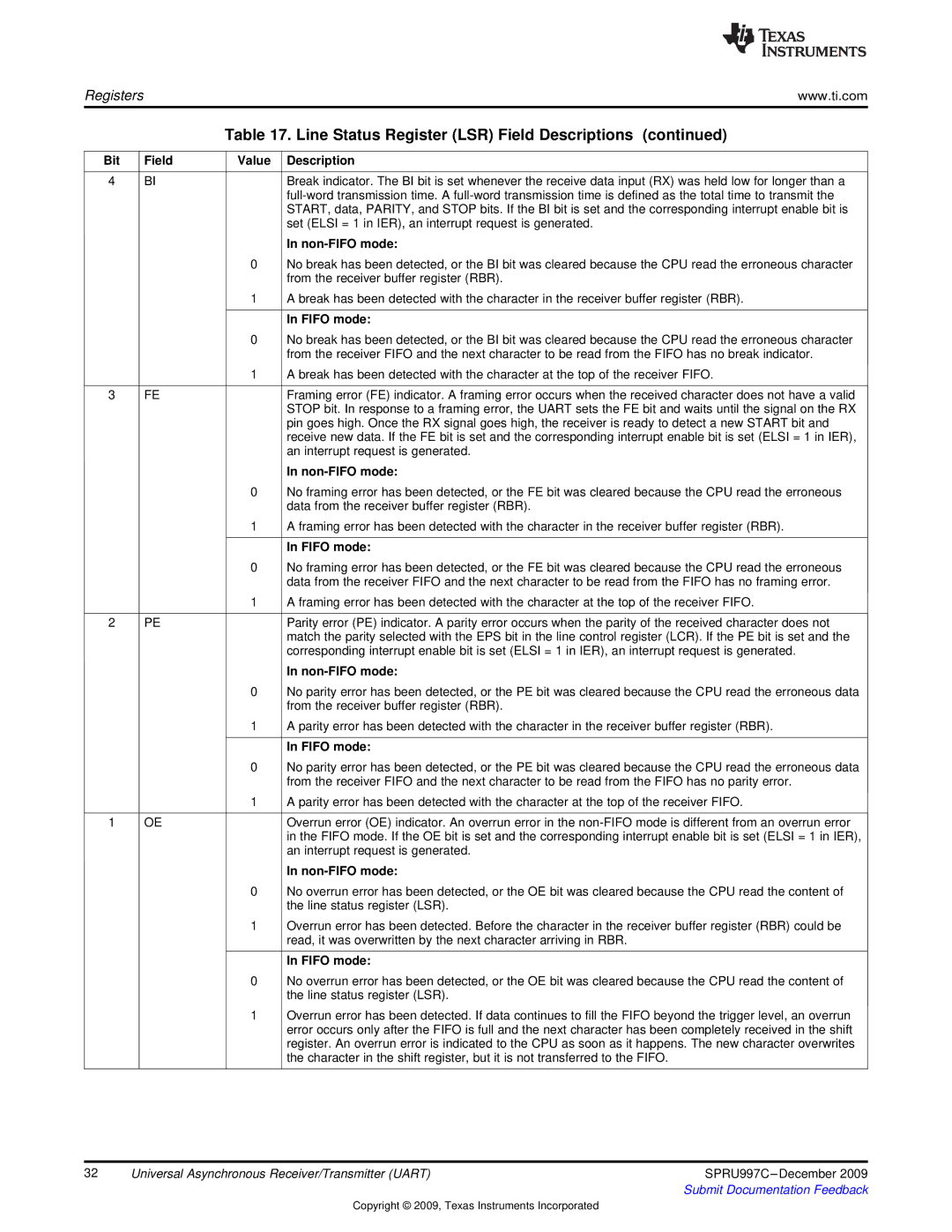
Table 17. Line Status Register (LSR) Field Descriptions (continued)
Bit | Field | Value Description |
4 | BI | Break indicator. The BI bit is set whenever the receive data input (RX) was held low for longer than a |
|
| |
|
| START, data, PARITY, and STOP bits. If the BI bit is set and the corresponding interrupt enable bit is |
|
| set (ELSI = 1 in IER), an interrupt request is generated. |
|
|
| In |
| 0 | No break has been detected, or the BI bit was cleared because the CPU read the erroneous character | |
|
|
| from the receiver buffer register (RBR). |
| 1 | A break has been detected with the character in the receiver buffer register (RBR). | |
|
|
|
|
|
|
| In FIFO mode: |
| 0 | No break has been detected, or the BI bit was cleared because the CPU read the erroneous character | |
|
|
| from the receiver FIFO and the next character to be read from the FIFO has no break indicator. |
| 1 | A break has been detected with the character at the top of the receiver FIFO. | |
|
|
| |
3 | FE | Framing error (FE) indicator. A framing error occurs when the received character does not have a valid | |
|
|
| STOP bit. In response to a framing error, the UART sets the FE bit and waits until the signal on the RX |
|
|
| pin goes high. Once the RX signal goes high, the receiver is ready to detect a new START bit and |
|
|
| receive new data. If the FE bit is set and the corresponding interrupt enable bit is set (ELSI = 1 in IER), |
|
|
| an interrupt request is generated. |
|
|
| In |
| 0 | No framing error has been detected, or the FE bit was cleared because the CPU read the erroneous | |
|
|
| data from the receiver buffer register (RBR). |
| 1 | A framing error has been detected with the character in the receiver buffer register (RBR). | |
|
|
|
|
|
|
| In FIFO mode: |
| 0 | No framing error has been detected, or the FE bit was cleared because the CPU read the erroneous | |
|
|
| data from the receiver FIFO and the next character to be read from the FIFO has no framing error. |
| 1 | A framing error has been detected with the character at the top of the receiver FIFO. | |
|
|
| |
2 | PE | Parity error (PE) indicator. A parity error occurs when the parity of the received character does not | |
|
|
| match the parity selected with the EPS bit in the line control register (LCR). If the PE bit is set and the |
|
|
| corresponding interrupt enable bit is set (ELSI = 1 in IER), an interrupt request is generated. |
|
|
| In |
| 0 | No parity error has been detected, or the PE bit was cleared because the CPU read the erroneous data | |
|
|
| from the receiver buffer register (RBR). |
| 1 | A parity error has been detected with the character in the receiver buffer register (RBR). | |
|
|
|
|
|
|
| In FIFO mode: |
| 0 | No parity error has been detected, or the PE bit was cleared because the CPU read the erroneous data | |
|
|
| from the receiver FIFO and the next character to be read from the FIFO has no parity error. |
| 1 | A parity error has been detected with the character at the top of the receiver FIFO. | |
|
|
| |
1 | OE | Overrun error (OE) indicator. An overrun error in the | |
|
|
| in the FIFO mode. If the OE bit is set and the corresponding interrupt enable bit is set (ELSI = 1 in IER), |
|
|
| an interrupt request is generated. |
|
|
| In |
| 0 | No overrun error has been detected, or the OE bit was cleared because the CPU read the content of | |
|
|
| the line status register (LSR). |
| 1 | Overrun error has been detected. Before the character in the receiver buffer register (RBR) could be | |
|
|
| read, it was overwritten by the next character arriving in RBR. |
|
|
|
|
|
|
| In FIFO mode: |
| 0 | No overrun error has been detected, or the OE bit was cleared because the CPU read the content of | |
|
|
| the line status register (LSR). |
| 1 | Overrun error has been detected. If data continues to fill the FIFO beyond the trigger level, an overrun | |
|
|
| error occurs only after the FIFO is full and the next character has been completely received in the shift |
|
|
| register. An overrun error is indicated to the CPU as soon as it happens. The new character overwrites |
|
|
| the character in the shift register, but it is not transferred to the FIFO. |
32 | Universal Asynchronous Receiver/Transmitter (UART) | SPRU997C |
|
| Submit Documentation Feedback |
Copyright © 2009, Texas Instruments Incorporated