Registers | www.ti.com |
3.11 Power and Emulation Management Register (PWREMU_MGMT)
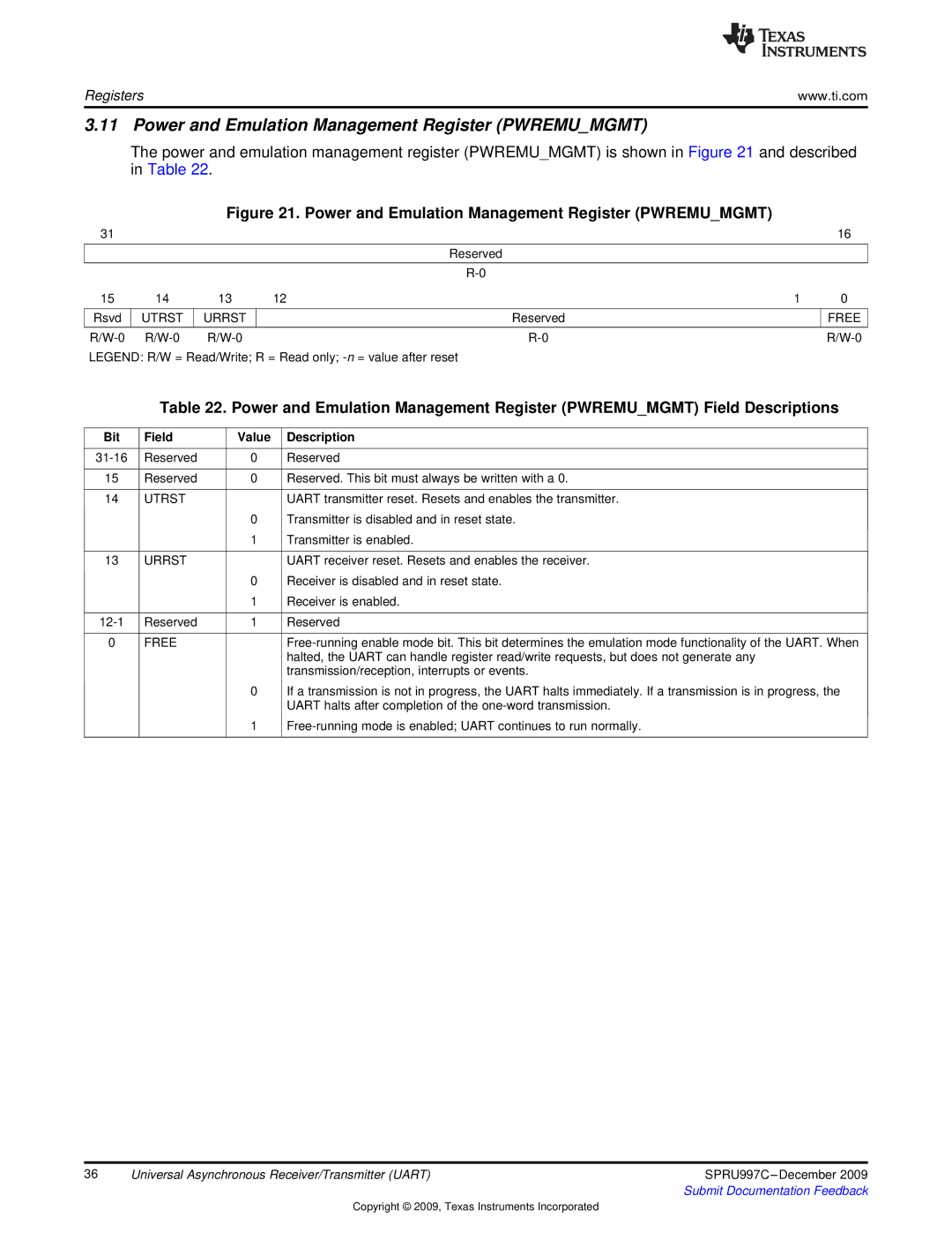
The power and emulation management register (PWREMU_MGMT) is shown in Figure 21 and described in Table 22.
Figure 21. Power and Emulation Management Register (PWREMU_MGMT)
31 |
|
|
|
| 16 |
|
|
|
| Reserved |
|
|
|
|
|
|
|
|
|
|
|
| |
15 | 14 | 13 | 12 | 1 | 0 |
|
|
|
|
|
|
Rsvd | UTRST | URRST |
| Reserved | FREE |
|
|
|
|
|
|
|
LEGEND: R/W = Read/Write; R = Read only;
Table 22. Power and Emulation Management Register (PWREMU_MGMT) Field Descriptions
Bit | Field | Value | Description |
|
|
|
|
Reserved | 0 | Reserved | |
|
|
|
|
15 | Reserved | 0 | Reserved. This bit must always be written with a 0. |
|
|
|
|
14 | UTRST |
| UART transmitter reset. Resets and enables the transmitter. |
|
| 0 | Transmitter is disabled and in reset state. |
|
| 1 | Transmitter is enabled. |
|
|
|
|
13 | URRST |
| UART receiver reset. Resets and enables the receiver. |
|
| 0 | Receiver is disabled and in reset state. |
|
| 1 | Receiver is enabled. |
|
|
|
|
Reserved | 1 | Reserved | |
|
|
|
|
0 | FREE |
| |
|
|
| halted, the UART can handle register read/write requests, but does not generate any |
|
|
| transmission/reception, interrupts or events. |
|
| 0 | If a transmission is not in progress, the UART halts immediately. If a transmission is in progress, the |
|
|
| UART halts after completion of the |
|
| 1 | |
|
|
|
|
36 | Universal Asynchronous Receiver/Transmitter (UART) | SPRU997C |
|
| Submit Documentation Feedback |
Copyright © 2009, Texas Instruments Incorporated
