TMS3320C5515 specifications
The Texas Instruments TMS3320C5515 is a highly specialized digital signal processor (DSP) designed for a wide range of applications, including telecommunications, audio processing, and other signal-intensive tasks. As part of the TMS320 family of DSPs, the TMS3320C5515 leverages TI's extensive experience in signal processing technology, delivering robust performance and reliability.One of the main features of the TMS3320C5515 is its 32-bit architecture, which allows for a high level of precision in digital signal computation. The processor is capable of executing complex mathematical algorithms, making it suitable for tasks that require high-speed data processing, such as speech recognition and audio filtering. With a native instruction set optimized for DSP applications, the TMS3320C5515 can perform multiply-accumulate operations in a single cycle, significantly enhancing computational efficiency.
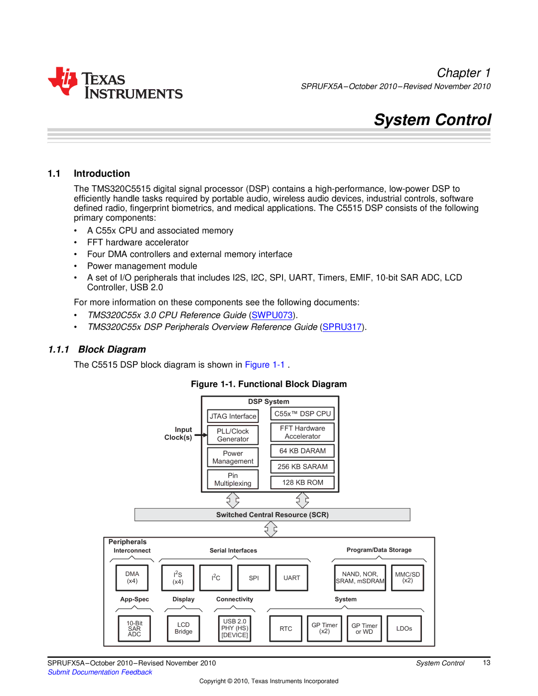
The TMS3320C5515 employs advanced technologies including a Harvard architecture that separates instruction and data memory, enabling simultaneous access and improving performance. Its dual data buses enhance throughput by allowing multi-channel processing, making it particularly effective for real-time applications where timely data manipulation is critical. The device supports a wide range of peripherals, facilitating connections to various sensors and communication systems, which is vital in embedded applications.
In terms of characteristics, the TMS3320C5515 operates at an impressive clock speed, providing the computational power necessary to handle demanding tasks. The device is optimized for low power consumption, making it ideal for battery-operated applications without sacrificing performance. Its flexibility in processing algorithms also allows it to be readily adapted for specific requirements, from audio codecs to modems.
Another noteworthy aspect is the extensive development ecosystem surrounding the TMS3320C5515, which includes software tools, libraries, and support resources designed to accelerate the development process. This allows engineers and developers to bring their projects to market more quickly while minimizing risk.
Overall, the Texas Instruments TMS3320C5515 stands out as a powerful DSP solution, equipped with features that cater to the needs of various industries. Its combination of performance, efficiency, and versatile application makes it an attractive choice for engineers working in signal processing.

