System Configuration and Control

www.ti.com


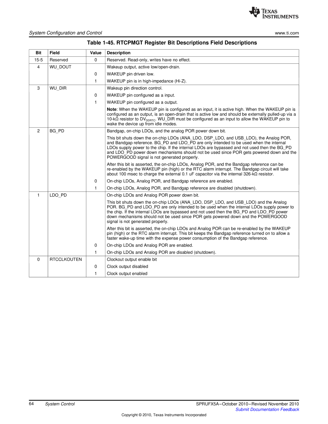
Table 1-45. RTCPMGT Register Bit Descriptions Field Descriptions


Bit

Field

Value

Description


15-5

Reserved

0

Reserved. Read-only, writes have no effect.


4

WU_DOUT


Wakeup output, active low/open-drain.


0

WAKEUP pin driven low.


1

WAKEUP pin is in high-impedance (Hi-Z).


3

WU_DIR


Wakeup pin direction control.


0

WAKEUP pin configured as a input.


1

WAKEUP pin configured as a output.


Note: When the WAKEUP pin is configured as an input, it is active high. When the WAKEUP pin is


configured as an output, is an open-drain that is active low and should be externally pulled-up via a


10-kΩresistor to DVDDRTC. WU_DIR must be configured as an input to allow the WAKEUP pin to


wake the device up from idle modes.


2

BG_PD


Bandgap, on-chip LDOs, and the analog POR power down bit.


This bit shuts down the on-chip LDOs (ANA_LDO, DSP_LDO, and USB_LDO), the Analog POR,


and Bandgap reference. BG_PD and LDO_PD are only intended to be used when the internal


LDOs supply power to the chip. If the internal LDOs are bypassed and not used then the BG_PD


and LDO_PD power down mechanisms should not be used since POR gets powered down and the


POWERGOOD signal is not generated properly.


After this bit is asserted, the on-chip LDOs, Analog POR, and the Bandgap reference can be


re-enabled by the WAKEUP pin (high) or the RTC alarm interrupt. The Bandgap circuit will take


about 100 msec to charge the external 0.1 uF capacitor via the internal 326-kΩresistor.


0

On-chip LDOs, Analog POR, and Bandgap reference are enabled.


1

On-chip LDOs, Analog POR, and Bandgap reference are disabled (shutdown).


1

LDO_PD


On-chip LDOs and Analog POR power down bit.


This bit shuts down the on-chip LDOs (ANA_LDO, DSP_LDO, and USB_LDO) and the Analog


POR. BG_PD and LDO_PD are only intended to be used when the internal LDOs supply power to


the chip. If the internal LDOs are bypassed and not used then the BG_PD and LDO_PD power


down mechanisms should not be used since POR gets powered down and the POWERGOOD


signal is not generated properly.


After this bit is asserted, the on-chip LDOs and Analog POR can be re-enabled by the WAKEUP


pin (high) or the RTC alarm interrupt. This bit keeps the Bandgap reference turned on to allow a


faster wake-up time with the expense power consumption of the Bandgap reference.


0

On-chip LDOs and Analog POR are enabled.


1

On-chip LDOs and Analog POR are disabled (shutdown).


0

RTCCLKOUTEN


Clockout output enable bit


0

Clock output disabled


1

Clock output enabled


64

System Control

SPRUFX5A –October 2010 –Revised November 2010


Submit Documentation Feedback

Copyright © 2010, Texas Instruments Incorporated

Page 64
Image 64
Texas Instruments TMS3320C5515 manual Rtcpmgt Register Bit Descriptions Field Descriptions, Bit Field

TMS3320C5515 specifications

The Texas Instruments TMS3320C5515 is a highly specialized digital signal processor (DSP) designed for a wide range of applications, including telecommunications, audio processing, and other signal-intensive tasks. As part of the TMS320 family of DSPs, the TMS3320C5515 leverages TI's extensive experience in signal processing technology, delivering robust performance and reliability.

One of the main features of the TMS3320C5515 is its 32-bit architecture, which allows for a high level of precision in digital signal computation. The processor is capable of executing complex mathematical algorithms, making it suitable for tasks that require high-speed data processing, such as speech recognition and audio filtering. With a native instruction set optimized for DSP applications, the TMS3320C5515 can perform multiply-accumulate operations in a single cycle, significantly enhancing computational efficiency.

The TMS3320C5515 employs advanced technologies including a Harvard architecture that separates instruction and data memory, enabling simultaneous access and improving performance. Its dual data buses enhance throughput by allowing multi-channel processing, making it particularly effective for real-time applications where timely data manipulation is critical. The device supports a wide range of peripherals, facilitating connections to various sensors and communication systems, which is vital in embedded applications.

In terms of characteristics, the TMS3320C5515 operates at an impressive clock speed, providing the computational power necessary to handle demanding tasks. The device is optimized for low power consumption, making it ideal for battery-operated applications without sacrificing performance. Its flexibility in processing algorithms also allows it to be readily adapted for specific requirements, from audio codecs to modems.

Another noteworthy aspect is the extensive development ecosystem surrounding the TMS3320C5515, which includes software tools, libraries, and support resources designed to accelerate the development process. This allows engineers and developers to bring their projects to market more quickly while minimizing risk.

Overall, the Texas Instruments TMS3320C5515 stands out as a powerful DSP solution, equipped with features that cater to the needs of various industries. Its combination of performance, efficiency, and versatile application makes it an attractive choice for engineers working in signal processing.