www.ti.comInterrupts

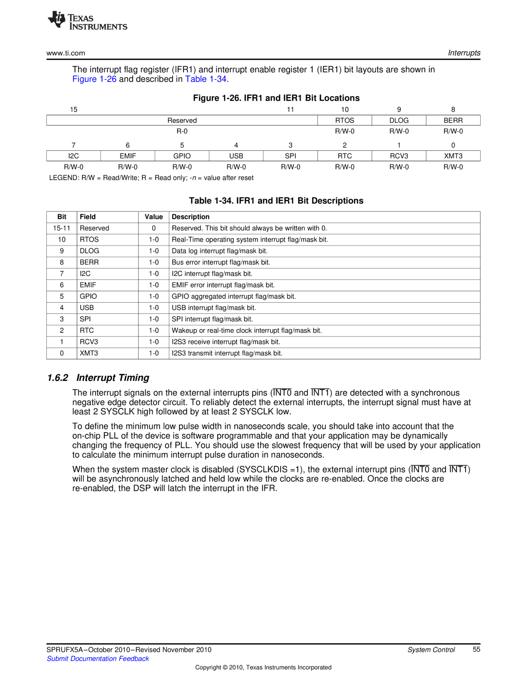
The interrupt flag register (IFR1) and interrupt enable register 1 (IER1) bit layouts are shown in Figure 1-26and described in Table 1-34.

Figure 1-26. IFR1 and IER1 Bit Locations

15


11

10

9

8


Reserved


RTOS

DLOG

BERR


R-0


R/W-0

R/W-0

R/W-0

7

6

5

4

3

2

1

0


I2C

EMIF

GPIO

USB

SPI

RTC

RCV3

XMT3


R/W-0

R/W-0

R/W-0

R/W-0

R/W-0

R/W-0

R/W-0

R/W-0

LEGEND: R/W = Read/Write; R = Read only; -n= value after reset


Table 1-34. IFR1 and IER1 Bit Descriptions


Bit

Field

Value

Description


15-11

Reserved

0

Reserved. This bit should always be written with 0.


10

RTOS

1-0

Real-Time operating system interrupt flag/mask bit.


9

DLOG

1-0

Data log interrupt flag/mask bit.


8

BERR

1-0

Bus error interrupt flag/mask bit.


7

I2C

1-0

I2C interrupt flag/mask bit.


6

EMIF

1-0

EMIF error interrupt flag/mask bit.


5

GPIO

1-0

GPIO aggregated interrupt flag/mask bit.


4

USB

1-0

USB interrupt flag/mask bit.


3

SPI

1-0

SPI interrupt flag/mask bit.


2

RTC

1-0

Wakeup or real-time clock interrupt flag/mask bit.


1

RCV3

1-0

I2S3 receive interrupt flag/mask bit.


0

XMT3

1-0

I2S3 transmit interrupt flag/mask bit.


1.6.2 Interrupt Timing

The interrupt signals on the external interrupts pins (INT0 and INT1) are detected with a synchronous negative edge detector circuit. To reliably detect the external interrupts, the interrupt signal must have at least 2 SYSCLK high followed by at least 2 SYSCLK low.

To define the minimum low pulse width in nanoseconds scale, you should take into account that the on-chip PLL of the device is software programmable and that your application may be dynamically changing the frequency of PLL. You should use the slowest frequency that will be used by your application to calculate the minimum interrupt pulse duration in nanoseconds.

When the system master clock is disabled (SYSCLKDIS =1), the external interrupt pins (INT0 and INT1) will be asynchronously latched and held low while the clocks are re-enabled. Once the clocks are re-enabled, the DSP will latch the interrupt in the IFR.

SPRUFX5A –October 2010 –Revised November 2010

System Control

55

Submit Documentation Feedback


Copyright © 2010, Texas Instruments Incorporated

Page 55
Image 55
Texas Instruments TMS3320C5515 manual Interrupt Timing, IFR1 and IER1 Bit Descriptions, Rtos

TMS3320C5515 specifications

The Texas Instruments TMS3320C5515 is a highly specialized digital signal processor (DSP) designed for a wide range of applications, including telecommunications, audio processing, and other signal-intensive tasks. As part of the TMS320 family of DSPs, the TMS3320C5515 leverages TI's extensive experience in signal processing technology, delivering robust performance and reliability.

One of the main features of the TMS3320C5515 is its 32-bit architecture, which allows for a high level of precision in digital signal computation. The processor is capable of executing complex mathematical algorithms, making it suitable for tasks that require high-speed data processing, such as speech recognition and audio filtering. With a native instruction set optimized for DSP applications, the TMS3320C5515 can perform multiply-accumulate operations in a single cycle, significantly enhancing computational efficiency.

The TMS3320C5515 employs advanced technologies including a Harvard architecture that separates instruction and data memory, enabling simultaneous access and improving performance. Its dual data buses enhance throughput by allowing multi-channel processing, making it particularly effective for real-time applications where timely data manipulation is critical. The device supports a wide range of peripherals, facilitating connections to various sensors and communication systems, which is vital in embedded applications.

In terms of characteristics, the TMS3320C5515 operates at an impressive clock speed, providing the computational power necessary to handle demanding tasks. The device is optimized for low power consumption, making it ideal for battery-operated applications without sacrificing performance. Its flexibility in processing algorithms also allows it to be readily adapted for specific requirements, from audio codecs to modems.

Another noteworthy aspect is the extensive development ecosystem surrounding the TMS3320C5515, which includes software tools, libraries, and support resources designed to accelerate the development process. This allows engineers and developers to bring their projects to market more quickly while minimizing risk.

Overall, the Texas Instruments TMS3320C5515 stands out as a powerful DSP solution, equipped with features that cater to the needs of various industries. Its combination of performance, efficiency, and versatile application makes it an attractive choice for engineers working in signal processing.