www.ti.com
VLYNQ Port Registers
3.2Control Register (CTRL)
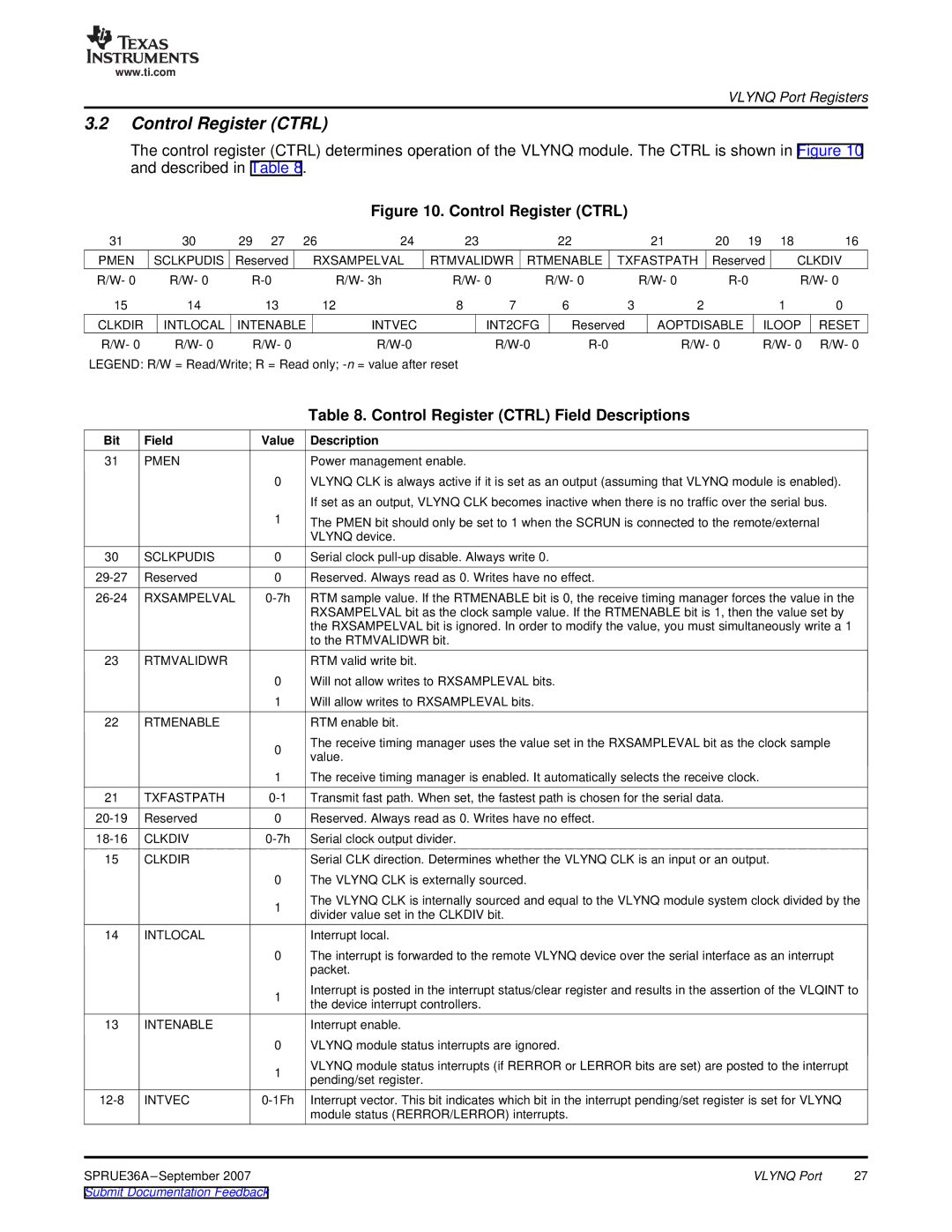
The control register (CTRL) determines operation of the VLYNQ module. The CTRL is shown in Figure 10 and described in Table 8.
Figure 10. Control Register (CTRL)
31 | 30 | 29 | 27 | 26 | 24 |
| 23 | 22 |
| 21 | 20 | 19 |
| 18 | 16 |
PMEN | SCLKPUDIS | Reserved | RXSAMPELVAL | RTMVALIDWR RTMENABLE | TXFASTPATH | Reserved | CLKDIV | ||||||||
R/W- 0 | R/W- 0 |
| R/W- 3h | R/W- 0 | R/W- 0 |
| R/W- 0 |
| R/W- 0 | ||||||
15 | 14 |
| 13 |
| 12 | 8 | 7 | 6 | 3 | 2 |
|
|
| 1 | 0 |
CLKDIR | INTLOCAL | INTENABLE | INTVEC |
| INT2CFG | Reserved | AOPTDISABLE |
| ILOOP | RESET | |||||
R/W- 0 | R/W- 0 |
| R/W- 0 |
|
|
| R/W- 0 |
| R/W- 0 | R/W- 0 | |||||
LEGEND: R/W = Read/Write; R = Read only; |
|
|
|
|
|
|
|
|
| ||||||
| Table 8. Control Register (CTRL) Field Descriptions |
Bit Field | Value Description |
31 PMEN
0
1
![]() Power management enable.
Power management enable.
VLYNQ CLK is always active if it is set as an output (assuming that VLYNQ module is enabled).
If set as an output, VLYNQ CLK becomes inactive when there is no traffic over the serial bus.
The PMEN bit should only be set to 1 when the SCRUN is connected to the remote/external VLYNQ device.
30 | SCLKPUDIS | 0 | Serial clock |
Reserved | 0 | Reserved. Always read as 0. Writes have no effect. | |
RXSAMPELVAL | RTM sample value. If the RTMENABLE bit is 0, the receive timing manager forces the value in the | ||
|
|
| RXSAMPELVAL bit as the clock sample value. If the RTMENABLE bit is 1, then the value set by |
|
|
| the RXSAMPELVAL bit is ignored. In order to modify the value, you must simultaneously write a 1 |
|
|
| to the RTMVALIDWR bit. |
23 | RTMVALIDWR |
| RTM valid write bit. |
|
| 0 | Will not allow writes to RXSAMPLEVAL bits. |
|
| 1 | Will allow writes to RXSAMPLEVAL bits. |
22 | RTMENABLE |
| RTM enable bit. |
|
| 0 | The receive timing manager uses the value set in the RXSAMPLEVAL bit as the clock sample |
|
| value. | |
|
|
| |
|
| 1 | The receive timing manager is enabled. It automatically selects the receive clock. |
21 | TXFASTPATH | Transmit fast path. When set, the fastest path is chosen for the serial data. | |
Reserved | 0 | Reserved. Always read as 0. Writes have no effect. | |
CLKDIV | Serial clock output divider. | ||
15 | CLKDIR |
| Serial CLK direction. Determines whether the VLYNQ CLK is an input or an output. |
|
| 0 | The VLYNQ CLK is externally sourced. |
|
| 1 | The VLYNQ CLK is internally sourced and equal to the VLYNQ module system clock divided by the |
|
| divider value set in the CLKDIV bit. | |
|
|
| |
14 | INTLOCAL |
| Interrupt local. |
|
| 0 | The interrupt is forwarded to the remote VLYNQ device over the serial interface as an interrupt |
|
|
| packet. |
1
13 INTENABLE
0
1
|
Interrupt is posted in the interrupt status/clear register and results in the assertion of the VLQINT to the device interrupt controllers.
![]() Interrupt enable.
Interrupt enable.
VLYNQ module status interrupts are ignored.
VLYNQ module status interrupts (if RERROR or LERROR bits are set) are posted to the interrupt pending/set register.
Interrupt vector. This bit indicates which bit in the interrupt pending/set register is set for VLYNQ module status (RERROR/LERROR) interrupts.
SPRUE36A | VLYNQ Port | 27 |
Submit Documentation Feedback |
|
|