FPS1000 Instruction Manual
4.11 Remote Sensing
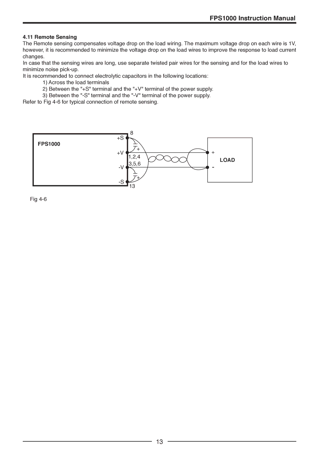
The Remote sensing compensates voltage drop on the load wiring. The maximum voltage drop on each wire is 1V, however, it is recommended to minimize the voltage drop on the load wires to improve the response to load current changes.
In case that the sensing wires are long, use separate twisted pair wires for the sensing and for the load wires to minimize noise
It is recommended to connect electrolytic capacitors in the following locations:
1)Across the load terminals
2)Between the "+S" terminal and the "+V" terminal of the power supply.
3)Between the
+S | 8 |
| |
|
| ||
FPS1000 | + |
| |
+V | + | ||
1,2,4 | |||
LOAD | |||
| 3,5,6 | ||
- | |||
+ |
| ||
13 |
|
Fig
13