10.7.3 Making the load connections
!WARNING
Hazardous voltages may exist at the outputs and the load connections when using a power supply with a rated output greater than 40V. To protect personnel against accidental contact with hazardous voltages, ensure that the load and it's connections has no accessible live parts. Ensure that the load wiring insulation rating is greater than or equal to the maximum output voltage of the power supply.
The load wires should be properly terminated with terminals securely attached. DO NOT use unterminated wires for load connection at the
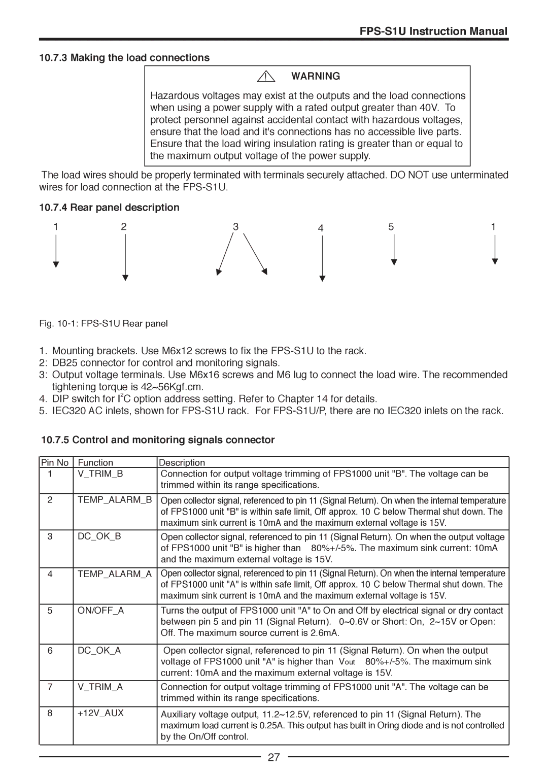
10.7.4 Rear panel description
1 | 2 | 3 | 4 | 5 | 1 |
Fig. 10-1: FPS-S1U Rear panel
1.Mounting brackets. Use M6x12 screws to fix the
2: DB25 connector for control and monitoring signals.
3: Output voltage terminals. Use M6x16 screws and M6 lug to connect the load wire. The recommended tightening torque is 42~56Kgf.cm.
4.DIP switch for I2C option address setting. Refer to Chapter 14 for details.
5.IEC320 AC inlets, shown for
10.7.5Control and monitoring signals connector
Pin No | Function | Description |
1 | V_TRIM_B | Connection for output voltage trimming of FPS1000 unit "B". The voltage can be |
|
| trimmed within its range specifications. |
|
|
|
2 | TEMP_ALARM_B | Open collector signal, referenced to pin 11 (Signal Return). On when the internal temperature |
|
| of FPS1000 unit "B" is within safe limit, Off approx. 10°C below Thermal shut down. The |
|
| maximum sink current is 10mA and the maximum external voltage is 15V. |
|
|
|
3 | DC_OK_B | Open collector signal, referenced to pin 11 (Signal Return). On when the output voltage |
|
| of FPS1000 unit "B" is higher than ≥ |
|
| and the maximum external voltage is 15V. |
|
|
|
4 | TEMP_ALARM_A | Open collector signal, referenced to pin 11 (Signal Return). On when the internal temperature |
|
| of FPS1000 unit "A" is within safe limit, Off approx. 10°C below Thermal shut down. The |
|
| maximum sink current is 10mA and the maximum external voltage is 15V. |
|
|
|
5 | ON/OFF_A | Turns the output of FPS1000 unit "A" to On and Off by electrical signal or dry contact |
|
| between pin 5 and pin 11 (Signal Return). 0~0.6V or Short: On, 2~15V or Open: |
|
| Off. The maximum source current is 2.6mA. |
|
|
|
6 | DC_OK_A | Open collector signal, referenced to pin 11 (Signal Return). On when the output |
|
| voltage of FPS1000 unit "A" is higher than Vout ≥ |
|
| current: 10mA and the maximum external voltage is 15V. |
|
|
|
7 | V_TRIM_A | Connection for output voltage trimming of FPS1000 unit "A". The voltage can be |
|
| trimmed within its range specifications. |
|
|
|
8 | +12V_AUX | Auxiliary voltage output, 11.2~12.5V, referenced to pin 11 (Signal Return). The |
|
| maximum load current is 0.25A. This output has built in Oring diode and is not controlled |
|
| by the On/Off control. |
|
|
|
27