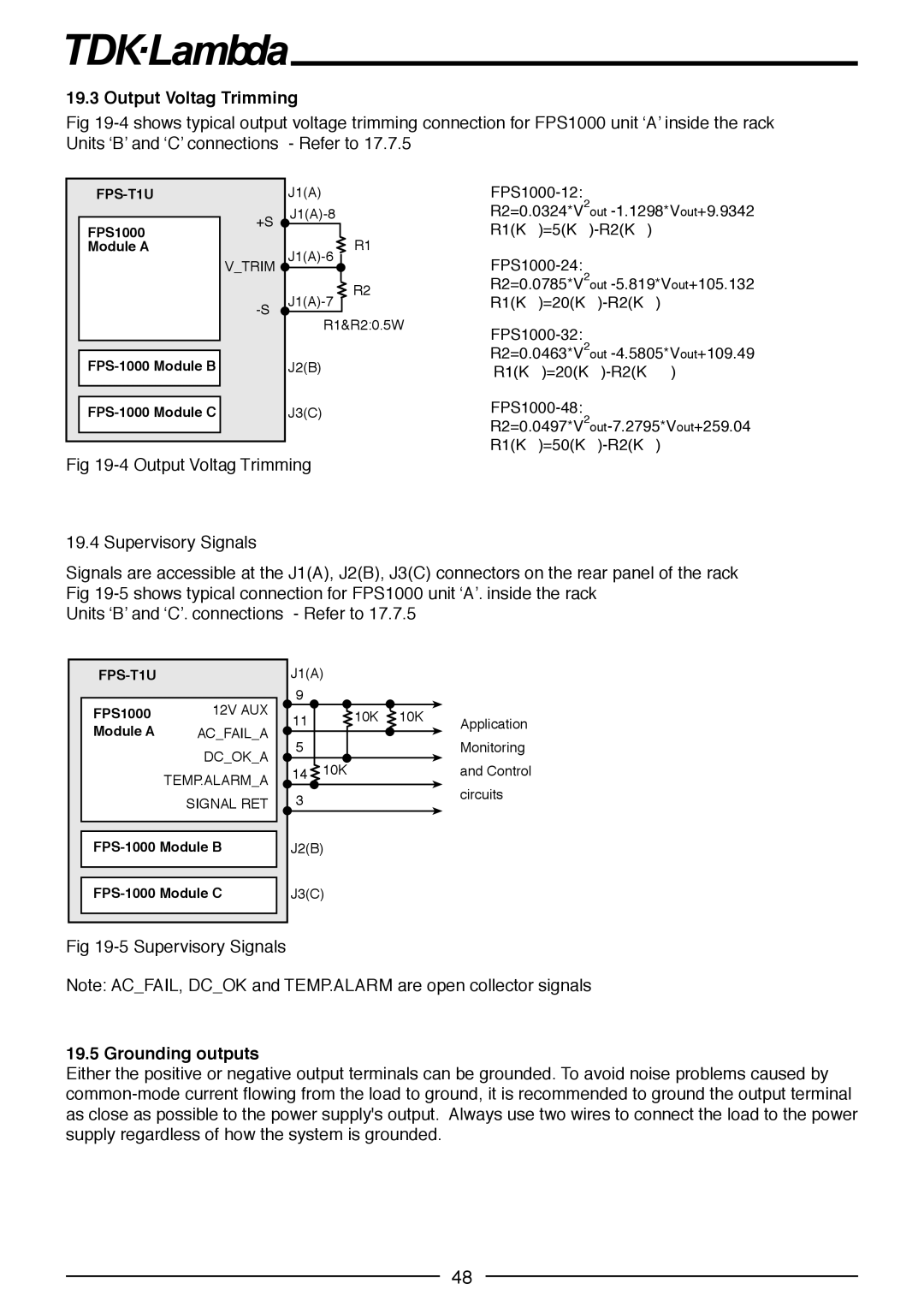
19.3 Output Voltag Trimming
Fig
FPS-T1U
+S
J1(A)
R2=0.0324*V2out
FPS1000 Module A
V_TRIM
R1
![]() R2
R2
R2=0.0785*V2out
R1&R2:0.5W
J2(B)
J3(C)
R2=0.0463*V2out
Fig
19.4 Supervisory Signals
Signals are accessible at the J1(A), J2(B), J3(C) connectors on the rear panel of the rack Fig
Units ‘B’ and ‘C’. connections - Refer to 17.7.5
FPS-T1U
FPS1000 | 12V AUX |
Module A | AC_FAIL_A |
| DC_OK_A |
| TEMP.ALARM_A |
| SIGNAL RET |
|
|
J1(A) |
|
| |
9 |
|
|
|
11 | 10K | 10K | Application |
|
| ||
5 |
|
| Monitoring |
14 | 10K |
| and Control |
3circuits
J2(B)
J3(C)
Fig
Note: AC_FAIL, DC_OK and TEMP.ALARM are open collector signals
19.5 Grounding outputs
Either the positive or negative output terminals can be grounded. To avoid noise problems caused by
48