12.4 On/Off control
Fig
When it is desired to control all the installed units simultaneously, it is possible to connect the On/Off control as shown in Fig
ON/OFF_A | 5 | ||
15 | |||
| ON/OFF_B | ||
| 25 | ||
| ON/OFF_C | ||
|
|
ON/ ON/ ON/
OFF OFF OFF
SIGNAL_RET 11
UNIT UNIT UNIT ‘C’ ‘B’ ‘A’
SIGNAL_RET
5
15
25
11
ON/
OFF
Fig | Fig |
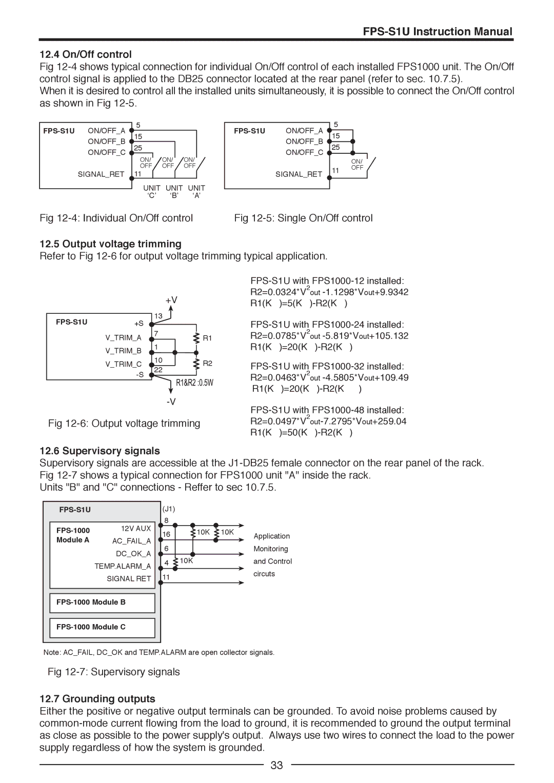
12.5 Output voltage trimming
Refer to Fig 12-6 for output voltage trimming typical application.
R2=0.0324*V2out
+VR1(KΩ)=5(KΩ)-R2(KΩ)
13
7
V_TRIM_A ![]()
![]() R1 V_TRIM_B 1
R1 V_TRIM_B 1
V_TRIM_C | 10 | R2 | |
22 | |||
| |||
|
|
Fig 12-6: Output voltage trimming
12.6 Supervisory signals
Supervisory signals are accessible at the
Units "B" and "C" connections - Reffer to sec 10.7.5.
| (J1) |
|
| |
| 12V AUX | 8 |
|
|
16 | 10K 10K | Application | ||
Module A | AC_FAIL_A |
| ||
6 |
| Monitoring | ||
| DC_OK_A |
| ||
| 4 10K |
| and Control | |
| TEMP.ALARM_A |
| ||
|
|
| circuts | |
| SIGNAL RET 11 |
| ||
|
|
| ||
Note: AC_FAIL, DC_OK and TEMP.ALARM are open collector signals.
Fig
12.7 Grounding outputs
Either the positive or negative output terminals can be grounded. To avoid noise problems caused by
33