FPS-S1U Instruction Manual
CHAPTER 14 FPS-S1U I2C BUS INTERFACE OPTION
14.1 Introduction
The FPS-S1U rack provides access to the I2C Bus interface in each installed FPS1000/S unit via the rear panel DB25 female connector located at the rear panel. The Clock is connected to pin 20 and the Data is connected to pin 21. The specifications of the I2C of the FPS1000/S power supplies are kept when they are installed in the FPS-S1U rack. Refer to Chapter 7 for the specifications and all operating details.
14.2 Addressing (A0, A1, A2).
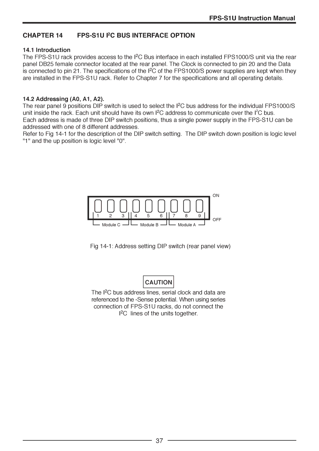
The rear panel 9 positions DIP switch is used to select the I2C bus address for the individual FPS1000/S unit inside the rack. Each unit should have its own I2C address to communicate over the I2C bus.
Each address is made of three DIP switch positions, thus a single power supply in the FPS-S1U can be addressed with one of 8 different addresses.
Refer to Fig 14-1 for the description of the DIP switch setting. The DIP switch down position is logic level "1" and the up position is logic level "0".
| 1 | 2 | 3 | | 4 | 5 | 6 | | 7 | 8 | 9 | |
| | | |
| | | | | | | | | | | | | | | |
| | Module C | | | | | Module B | | | | | Module A | | | |
| | | | | | | | | | | | |
Fig 14-1: Address setting DIP switch (rear panel view)
CAUTION
The I2C bus address lines, serial clock and data are referenced to the -Sense potential. When using series connection of FPS-S1U racks, do not connect the I2C lines of the units together.