17.7.3 Making the load connections
!WARNING
Hazardous voltages may exist at the outputs and the load connections when using a power supply with a rated output greater than 40V. To protect personnel against accidental contact with hazardous voltages, ensure that the load and it's connections has no accessible live parts. Ensure that the load wiring insulation rating is greater than or equal to the maximum output voltage of the power supply.
The load wires should be properly terminated with terminals securely attached. DO NOT use unterminated wires for load connection at the
17.7.4 Rear panel description
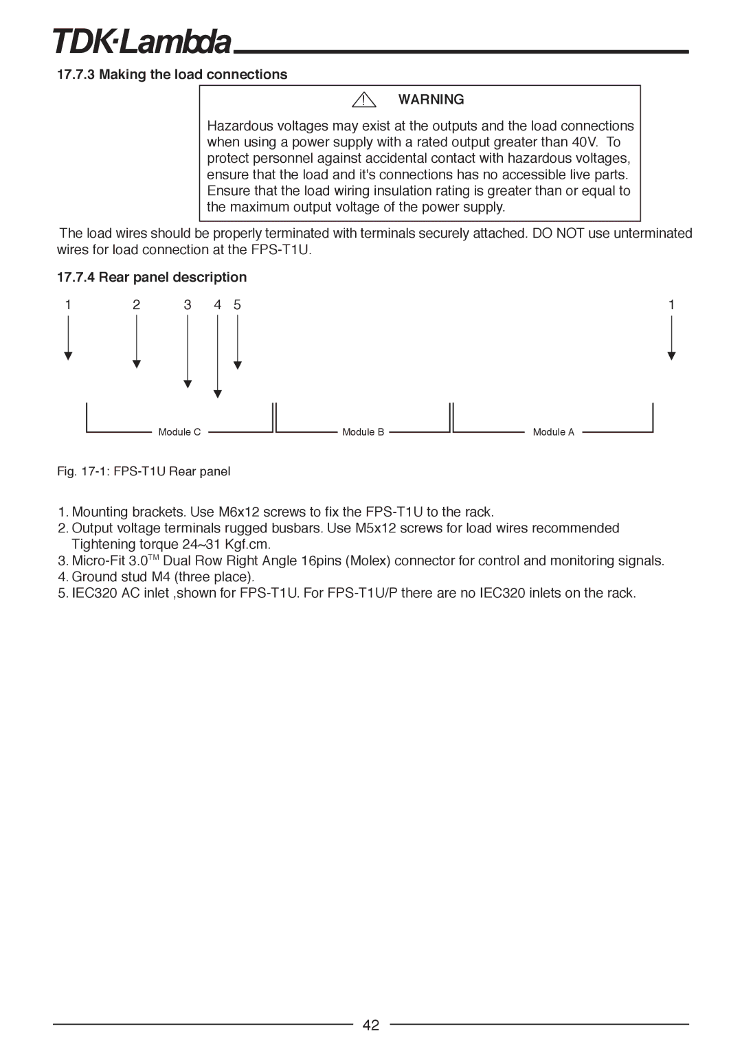
1 | 2 | 3 | 4 | 5 | 1 |
Module C
Fig. 17-1: FPS-T1U Rear panel
Module B
Module A
1.Mounting brackets. Use M6x12 screws to fix the
2.Output voltage terminals rugged busbars. Use M5x12 screws for load wires recommended Tightening torque 24~31 Kgf.cm.
3.
4.Ground stud M4 (three place).
5.IEC320 AC inlet ,shown for
42