CHAPTER 12 BASIC CONNECTIONS FOR OPERATION FPS-S1U RACK
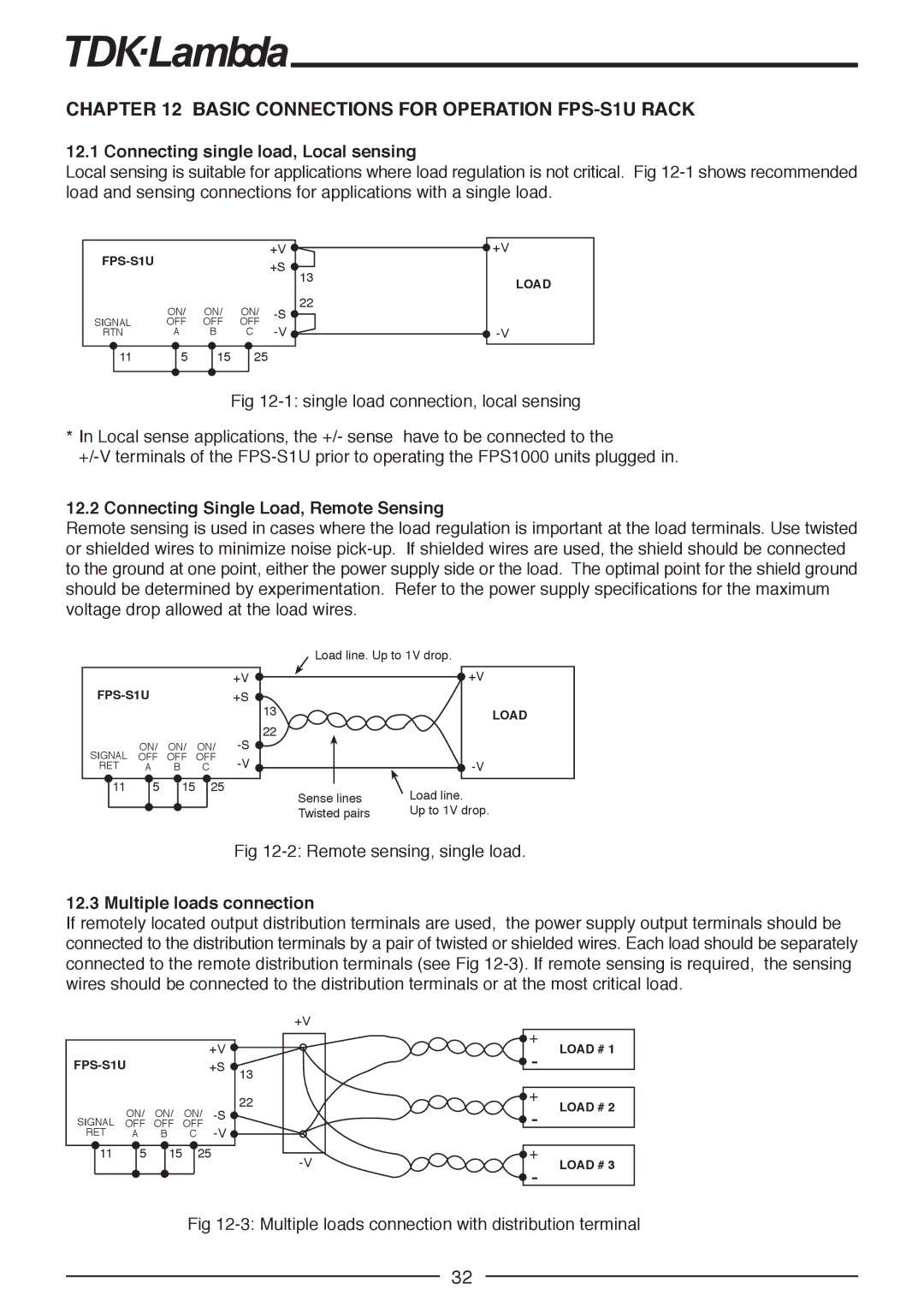
12.1 Connecting single load, Local sensing
Local sensing is suitable for applications where load regulation is not critical. Fig
|
|
| +V |
| +V | |
|
|
| +S |
|
| |
|
|
|
| 13 |
| |
|
|
|
|
| LOAD | |
|
|
|
|
|
| |
| ON/ | ON/ | ON/ | 22 |
| |
SIGNAL |
|
| ||||
OFF | OFF | OFF |
|
| ||
RTN | A | B | C |
| ||
11 | 5 | 15 | 25 |
|
|
|
Fig
*In Local sense applications, the +/- sense have to be connected to the
12.2 Connecting Single Load, Remote Sensing
Remote sensing is used in cases where the load regulation is important at the load terminals. Use twisted or shielded wires to minimize noise
+V
SIGNAL | ON/ | ON/ | ON/ | |||||
OFF | OFF | OFF | ||||||
RET | A | B | C | |||||
|
| 5 |
| 15 |
|
|
| |
| 11 |
|
|
| 25 |
| ||
|
|
|
|
|
|
|
|
|
Load line. Up to 1V drop.
| +V |
13 | * |
LOAD | |
22 |
|
| |
Sense lines | Load line. |
Twisted pairs | Up to 1V drop. |
Fig
12.3 Multiple loads connection
If remotely located output distribution terminals are used, the power supply output terminals should be connected to the distribution terminals by a pair of twisted or shielded wires. Each load should be separately connected to the remote distribution terminals (see Fig
+V
|
|
|
| +V |
|
|
| +S | 13 | ||
|
|
|
|
| |
| ON/ ON/ ON/ | 22 | |||
SIGNAL |
| ||||
OFF | OFF | OFF |
| ||
RET | A | B | C |
| |
11 | 5 | 15 | 25 | ||
|
|
|
|
| |
![]() +
+
-LOAD # 1
![]() +
+
-LOAD # 2
![]() +
+
-LOAD # 3
Fig
32