FPS1000 Instruction Manual
3.7.3 Noise and Impedance Effects
To minimize the noise pickup or radiation, the load wires and remote sense wires should be
Twisting the load wires reduces the parasitic inductance of the cable which could produce high frequency voltage spikes at the load and the output of power supply because of current variation in the load itself. The impedance introduced between the power supply output and the load could make the ripple and noise at the load worse than the noise at the power supply rear panel output. Additional filtering with bypass capacitors at the load terminals may be required to bypass the high frequency load current.
3.7.4 Inductive loads
To prevent damage to the power supply from inductive kickback, a diode should be connected across the output. The diode voltage and current rating should be greater than the power supply maximum output voltage and current rating. Connect the cathode to the positive output and the anode to the negative output. Where positive load transients such as back EMF from a motor may occur, connect a surge suppressor across the output to protect the power supply. The breakdown voltage rating of the suppressor must be approximately 10% higher than the maximum output voltage of the power supply.
3.7.5 Making the load connections
!WARNING
Hazardous voltages may exist at the outputs and the load connections when using a power supply with a rated output greater than 40V. To protect personnel against accidental contact with hazardous voltages, ensure that the load and it's connections has no accessible live parts.
Ensure that the load wiring insulation rating is greater than or equal to the maximum output voltage of the power supply.
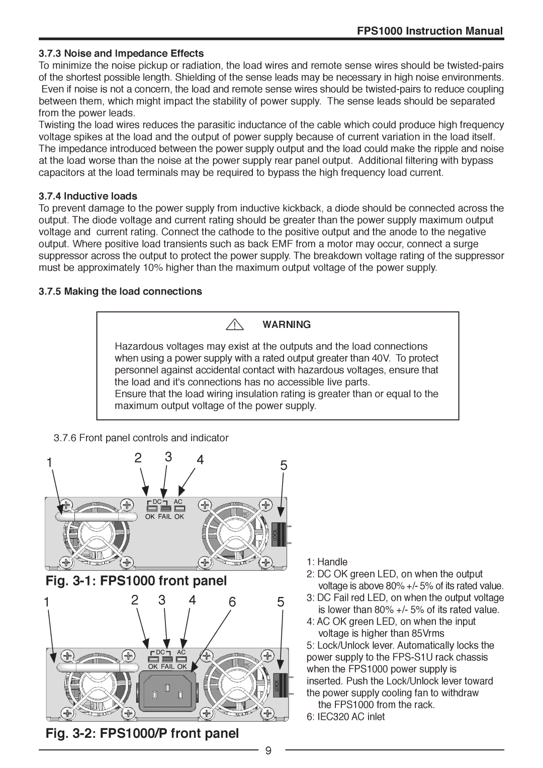
| 3.7.6 Front panel controls and indicator |
| |||||
1 | 2 |
|
| 3 | 4 | 5 | |
|
|
|
| ||||
|
|
|
|
|
|
|
|
|
|
|
|
|
|
|
|
Fig. 3-1: FPS1000 front panel
1 | 2 | 3 | 4 | 6 | 5 | ||
|
|
|
|
|
|
|
|
|
|
|
|
|
|
|
|
1:Handle
2:DC OK green LED, on when the output voltage is above 80% +/- 5% of its rated value.
3:DC Fail red LED, on when the output voltage is lower than 80% +/- 5% of its rated value.
4:AC OK green LED, on when the input voltage is higher than 85Vrms
5:Lock/Unlock lever. Automatically locks the power supply to the
the FPS1000 from the rack.
6:IEC320 AC inlet
Fig. 3-2: FPS1000/P front panel
9