FPS-T1U Instruction Manual
CHAPTER 19 BASIC CONNECTIONS FOR OPERATION FPS-T1U RACK
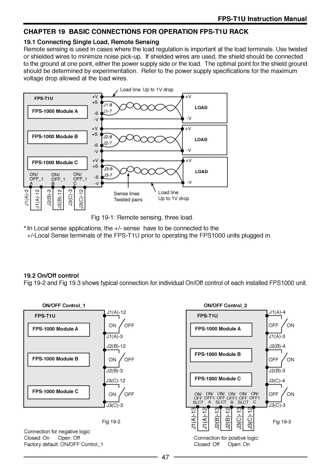
19.1 Connecting Single Load, Remote Sensing
Remote sensing is used in cases where the load regulation is important at the load terminals. Use twisted or shielded wires to minimize noise pick-up. If shielded wires are used, the shield should be connected to the ground at one point, either the power supply side or the load. The optimal point for the shield ground should be determined by experimentation. Refer to the power supply specifications for the maximum voltage drop allowed at the load wires.
| | FPS-1000 Module A | | | -S |
| | | | | | | | | | | |
| | | | | | | | | | | | -V |
| | | | | | | | | | | |
| | | | | | | | | | | | +V |
| | FPS-1000 Module B | | | +S |
| | | | |
| | | | | | | | | | | | -S |
| | | | | | | | | | | |
| | | | | | | | | | | | -V |
| | | | | | | | | | | | +V |
| | FPS-1000 Module C | | |
| | | | +S |
| | | | | | | | | | | |
| | | | | | | | | | | |
| ON/ | | ON/ | ON/ | -S |
| OFF_1 | | OFF_1 | OFF_1 |
| | |
| A | | B | C | | | -V |
J1(A)-3 | | J1(A)-12 | | J2(B)-3 | | J2(B)-12 | | J3(C)-3 | | J3(C)-12 | | |
| | | | | | | | | | | | |
Load line. Up to 1V drop.
| | +V |
| J1-8 | LOAD |
| J1-7 |
| |
| | -V |
| | +V |
| J2-8 | LOAD |
| J2-7 |
| |
| | -V |
| | +V |
| J3-8 | LOAD |
| J3-7 |
| |
| | -V |
| Sense lines | Load line. |
| Twisted pairs | Up to 1V drop. |
Fig 19-1: Remote sensing, three load.
*In Local sense applications, the +/- sense have to be connected to the
+/-Local Sense terminals of the FPS-T1U prior to operating the FPS1000 units plugged in.
19.2 On/Off control
Fig 19-2 and Fig 19.3 shows typical connection for individual On/Off control of each installed FPS1000 unit.
ON/OFF Control_1
FPS-T1U
FPS-1000 Module A
FPS-1000 Module B
FPS-1000 Module C
J1(A)-12
ON OFF J1(A)-3 J2(B)-12
ON OFF J2(B)-3 J3(C)-12
ON OFF J3(C)-3
Fig 19-2
ON/OFF Control_2
FPS-T1U
FPS-1000 Module A
FPS-1000 Module B
FPS-1000 Module C
ON/ ON/ ON/ ON/ ON/ ON/
OFF OFF1 OFF OFF1 OFF OFF1 SLCT A SLCT B SLCT C
J1(A)-13 | J1(A)-12 | J2(B)-13 | J2(B)-12 | J3(C)-13 | J3(C)-12 |
J1(A)-4
OFF ON J1(A)-3 J2(B)-4
OFF ON J2(B)-3 J3(C)-4
OFF ON J3(C)-3
Fig 19-3
Connection for negative logic: Closed: On Open: Off Factory default: ON/OFF Control_1
Connection for positive logic: Closed: Off Open: On