FPS-T1U Instruction Manual
CHAPTER 21 FPS-T1U I2C BUS INTERFACE OPTION
21.1 Introduction
The FPS-T1U rack provides access to the I2C Bus interface in each installed FPS1000/S unit via the rear panel MOLEX female connector located at the rear panel. The Clock is connected to pin 2 and the Data is connected to pin 1. The specifications of the I2C of the FPS1000/S power supplies are kept when they are installed in the FPS-T1U rack. Refer to Chapter 7 for the specifications and all operating details.
21.2 Addressing (A0, A1, A2).
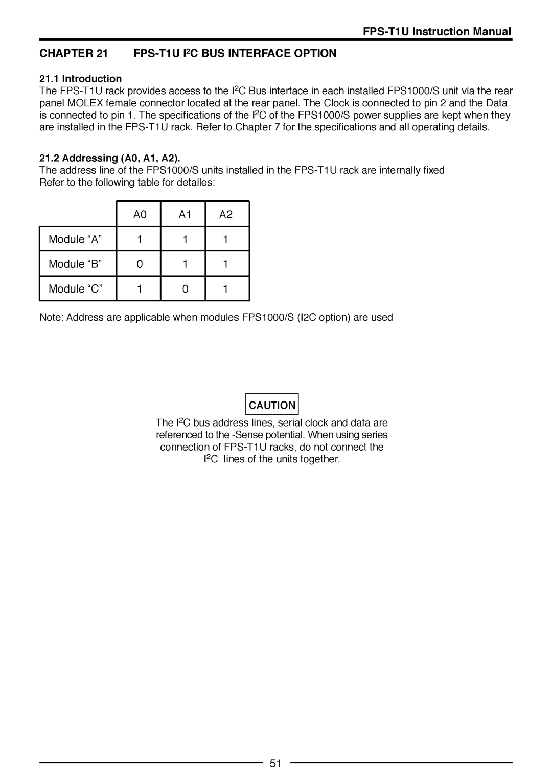
The address line of the FPS1000/S units installed in the FPS-T1U rack are internally fixed Refer to the following table for detailes:
| A0 | A1 | A2 |
| | | |
Module “A” | 1 | 1 | 1 |
| | | |
Module “B” | 0 | 1 | 1 |
| | | |
Module “C” | 1 | 0 | 1 |
| | | |
Note: Address are applicable when modules FPS1000/S (I2C option) are used
CAUTION
The I2C bus address lines, serial clock and data are referenced to the -Sense potential. When using series connection of FPS-T1U racks, do not connect the I2C lines of the units together.