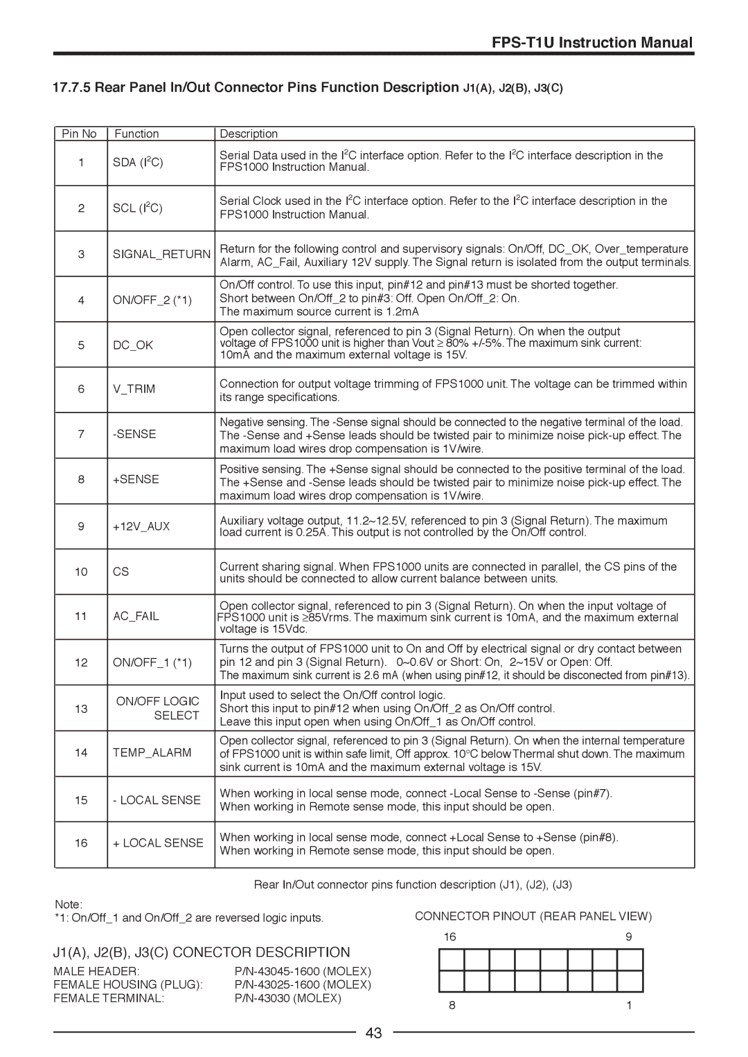
17.7.5 Rear Panel In/Out Connector Pins Function Description J1(A), J2(B), J3(C)
Pin No | Function | Description |
|
|
|
|
|
|
|
|
|
|
| ||
1 | 2 | C) | Serial Data used in the I2C interface option. Refer to the I2C interface description in the | ||||||||||||
SDA (I | FPS1000 Instruction Manual. |
|
|
|
|
|
|
|
|
|
|
| |||
|
|
|
|
|
|
|
|
|
|
|
|
|
| ||
|
|
|
|
|
|
|
|
|
|
|
|
| |||
2 | 2 | C) | Serial Clock used in the I2C interface option. Refer to the I2C interface description in the | ||||||||||||
SCL (I | FPS1000 Instruction Manual. |
|
|
|
|
|
|
|
|
|
|
| |||
|
|
|
|
|
|
|
|
|
|
|
|
|
| ||
|
|
|
|
|
|
|
|
|
|
|
| ||||
3 | SIGNAL_RETURN | Return for the following control and supervisory signals: On/Off, DC_OK, Over_temperature | |||||||||||||
|
|
| Alarm, AC_Fail, Auxiliary 12V supply. The Signal return is isolated from the output terminals. | ||||||||||||
|
|
|
|
|
|
|
|
|
|
|
|
| |||
|
|
| On/Off control. To use this input, pin#12 and pin#13 must be shorted together. | ||||||||||||
4 | ON/OFF_2 (*1) | Short between On/Off_2 to pin#3: Off. Open On/Off_2: On. | |||||||||||||
|
|
| The maximum source current is 1.2mA |
|
|
|
|
|
|
| |||||
|
|
|
|
|
|
|
|
|
|
|
|
| |||
|
|
| Open collector signal, referenced to pin 3 (Signal Return). On when the output | ||||||||||||
5 | DC_OK | voltage of FPS1000 unit is higher than Vout ≥ 80% | |||||||||||||
|
|
| 10mA and the maximum external voltage is 15V. |
|
|
|
|
|
|
| |||||
|
|
|
|
|
|
|
|
|
|
|
|
| |||
6 | V_TRIM | Connection for output voltage trimming of FPS1000 unit. The voltage can be trimmed within | |||||||||||||
its range specifications. |
|
|
|
|
|
|
|
|
|
|
| ||||
|
|
|
|
|
|
|
|
|
|
|
|
|
| ||
|
|
|
|
|
|
|
|
|
|
|
|
| |||
7 |
| Negative sensing. The | |||||||||||||
The | |||||||||||||||
|
|
| maximum load wires drop compensation is 1V/wire. |
|
|
|
|
|
|
| |||||
|
|
|
|
|
|
|
|
|
|
|
|
| |||
8 | +SENSE | Positive sensing. The +Sense signal should be connected to the positive terminal of the load. | |||||||||||||
The +Sense and | |||||||||||||||
|
|
| maximum load wires drop compensation is 1V/wire. |
|
|
|
|
|
|
| |||||
9 | +12V_AUX | Auxiliary voltage output, 11.2~12.5V, referenced to pin 3 (Signal Return). The maximum | |||||||||||||
load current is 0.25A. This output is not controlled by the On/Off control. | |||||||||||||||
|
|
| |||||||||||||
|
|
|
|
|
|
|
|
|
|
|
|
| |||
10 | CS |
| Current sharing signal. When FPS1000 units are connected in parallel, the CS pins of the | ||||||||||||
| units should be connected to allow current balance between units. | ||||||||||||||
|
|
| |||||||||||||
|
|
|
|
|
|
|
|
|
|
|
|
| |||
11 | AC_FAIL | Open collector signal, referenced to pin 3 (Signal Return). On when the input voltage of | |||||||||||||
FPS1000 unit is ≥85Vrms. The maximum sink current is 10mA, and the maximum external | |||||||||||||||
|
|
| voltage is 15Vdc. |
|
|
|
|
|
|
|
|
|
|
| |
|
|
|
|
|
|
|
|
|
|
|
|
| |||
|
|
| Turns the output of FPS1000 unit to On and Off by electrical signal or dry contact between | ||||||||||||
12 | ON/OFF_1 (*1) | pin 12 and pin 3 (Signal Return). | 0~0.6V or Short: On, | 2~15V or Open: Off. | |||||||||||
|
|
| The maximum sink current is 2.6 mA (when using pin#12, it should be disconected from pin#13). | ||||||||||||
|
|
|
|
|
|
|
|
|
|
|
|
|
| ||
| ON/OFF LOGIC | Input used to select the On/Off control logic. |
|
|
|
|
|
|
| ||||||
13 | Short this input to pin#12 when using On/Off_2 as On/Off control. | ||||||||||||||
| SELECT | ||||||||||||||
|
| Leave this input open when using On/Off_1 as On/Off control. | |||||||||||||
|
|
| |||||||||||||
|
|
|
|
|
|
|
|
|
|
|
|
| |||
14 | TEMP_ALARM | Open collector signal, referenced to pin 3 (Signal Return). On when the internal temperature | |||||||||||||
of FPS1000 unit is within safe limit, Off approx. 10°C below Thermal shut down. The maximum | |||||||||||||||
|
|
| sink current is 10mA and the maximum external voltage is 15V. | ||||||||||||
|
|
|
|
|
|
|
|
|
|
|
|
| |||
15 | - LOCAL SENSE | When working in local sense mode, connect | |||||||||||||
When working in Remote sense mode, this input should be open. | |||||||||||||||
|
|
| |||||||||||||
|
|
|
|
|
|
|
|
|
|
|
|
| |||
16 | + LOCAL SENSE | When working in local sense mode, connect +Local Sense to +Sense (pin#8). | |||||||||||||
When working in Remote sense mode, this input should be open. | |||||||||||||||
|
|
| |||||||||||||
|
|
|
|
|
|
|
|
|
|
|
|
| |||
|
|
| Rear In/Out connector pins function description (J1), (J2), (J3) | ||||||||||||
Note: |
|
|
| CONNECTOR PINOUT (REAR PANEL VIEW) | |||||||||||
*1: On/Off_1 and On/Off_2 are reversed logic inputs. | |||||||||||||||
|
|
|
| 16 |
|
| 9 |
| |||||||
J1(A), J2(B), J3(C) CONECTOR DESCRIPTION |
|
|
|
|
|
|
|
|
|
|
| ||||
|
|
|
|
|
|
|
|
|
|
| |||||
MALE HEADER: |
|
|
|
|
|
|
|
|
|
|
|
| |||
|
|
|
|
|
|
|
|
|
|
|
| ||||
FEMALE HOUSING (PLUG): |
|
|
|
|
|
|
|
|
|
|
| ||||
FEMALE TERMINAL: | 8 |
|
| 1 |
| ||||||||||
|
|
|
|
|
|
| |||||||||
43