Toro Company 1997, 1998, 2003
Preface
Groundsmaster 3000/3000-D
Table Of Contents
Groundsmaster 3000/3000-D
84I Cutting Units 72I Cutting Units
Contour 82I Cutting Unit Electrical Diagrams
Groundsmaster 3000/3000-D
Chapter
Safety Instructions
Before Operating
While Operating
Safety Groundsmaster 3000/3000-D
Maintenance
Safety 1 4 Rev. a Groundsmaster 3000/3000-D
Safety and Instruction Decals Groundsmaster
On Control Panel
Groundsmaster 3000/3000-D 1 5 Rev. a Safety
Safety and Instruction Decals Groundsmaster 3000-D
Safety 1 6 Rev. a
Safety and Instruction Decals 84I Cutting Units
On Each Castor Arm On Deck Channels, Under Covers
1 7 Rev. a Safety
On Rear of Deck On Front of Deck On Rear Of Deck
On Each Castor Arm
On Top of Rear Castor Chambers 2
Safety and Instruction Decals Contour 82I Cutting Unit
On Front Deck Hanger
Groundsmaster 3000/3000-D Safety
Deck On Each Corner On Right Rear Top of Deck Under Cover
On Gearbox Base On Front of Deck
On Front of Deck On Rear Of Deck
Safety Groundsmaster 3000/3000-D
Product Records
Product Records and Maintenance
Equivalents and Conversions
Product Records and Maintenance Groundsmaster 3000/3000-D
Torque Specifications
Product Records and Maintenance 2 4 Rev. a
Traction Unit
Lubrication
Cutting Units
Contour 82I Cutting Unit
Rear Discharge 84I Cutting Unit
Page
Equipment Operation and Service History Report
Annual Recommendations
GroundsmasterR3000 Maintenance Schedule
Maintenance Daily Maintenance Check For Week Check Item b
GroundsmasterR3000 Daily Maintenance Check List
B Service Required
Service Required
Records
Groundsmasterr 3000-D
Product Records and Maintenance 2 14 Rev. B
GroundsmasterR3000-D Maintenance Schedule
GroundsmasterR3000-D Daily Maintenance Check List
2 16 Rev. a
Service every 100 hours
C, and D Service Required
Service
Groundsmaster Ford VSG-411 Engine
Ford VSG-411 Engine
Ford VSG-411 Engine 3 2 Rev. a Groundsmaster
General Information Specifications
Cooling & Governor Fan Belts
Adjustments
Belt Adjustments
Alternator Belt
Ford VSG-411 Engine Groundsmaster
Governor Adjustment
Single Viscosity Oils
Service and Repairs
Outside Temperature
Check Engine Oil
Change Engine Oil and Filter
Check Coolant
Maintaining Cooling System Capacity
Cooling System Service
Compressed Air Method
General Air Cleaner Service
Service Air Cleaner
Washing Method
Fuel Tank
Fuel System Service
Fuel Lines and Connections
Check Governor Oil Level
Replacing Spark Plugs
Servicing Spark Arrestor Muffler
Peugeot TUD5 Engine
Peugeot TUD5 Engine
Peugeot TUD5 Engine Groundsmaster 3000-D
Valve Spring Compression Tool TOR4024T
Air Filter Element Cleaner TOR277220
Special Tools
Compression Test Kit TOR3003A
Order separately
Peugeot TUD5 Diesel Engine Service Tool Kit TOR4080
Injection Nozzle Tester TOR463610
Digital Belt Tension Tool TOR4075
Injector Socket TOR4082
Valve Guide Seal Remover TOR4081
Torque Angle Gauge TOR4083
Rear Main Seal Installer TOR4086
Camshaft Pinion Setting Tool TOR4084
Timing Pin Set TOR4085
Camshaft Seal Installer TOR4088
Front Seal Installer TOR4087
Fan Belt
Engine Belts
Not Overfill
Change Engine Oil and Filter
El. Coolant level should be up to or above tabs In de
Check Cooling System
Rear Screen Oil Cooler Radiator
Servicing the Air Cleaner
General Air Cleaner Maintenance
Changing Fuel Filter
Area. Always fill fuel tank outside and wipe
Up any spilled diesel fuel before starting
Draining Fuel Filter / Water Separator
Priming Fuel System
Frame, Fuel Tank and Battery
Muffler and Bumper
Hood
Rops
Center Shroud and Air Cleaner
Fan Bracket and Degasser
4 21 Rev. a Peugeot TUD5 Engine
Radiator and Cooler
Engine
Peugeot TUD5 Overhaul, Checking Tuning
Peugeot TUD5 Engine Groundsmaster 3000-D
Hydraulic System
Hydraulic System and Transaxle
Hydraulic System 5 2 Rev. a
Pushing or Towing Traction Unit
General Information
Hydraulic Hoses
Hydraulic Fitting Installation
Ring Face Seal
SAE Straight Thread O-Ring Port Adjustable
SAE Straight Thread O-Ring Port Non-adjustable
Lift OFF Hold LOWER/FLOAT
Hydraulic Schematic
Hydraulic System Transaxle
5 7 Rev. a Hydraulic System
Hydraulic System Groundsmaster 3000/3000-D
Hydraulic Components
Hydraulic Test Fitting Kit TOR4079
Hydraulic Pressure Test Kit TOR47009
Measuring Container TOR4077
Hydraulic System Groundsmaster 3000/3000-D
Testing
Charge Pressure Priority Valve Test
Charge Pressure Test
Reverse Traction Test
Forward Traction Test
Implement Relief Pressure Test
5 15 Rev. a Hydraulic System
Counterbalance Pressure Test and Adjustment
Hydraulic System 5 16 Rev. a
Steering Circuit Test
Cylinder Test
Steering Valve Test
Use a tester with pressure and flow capabilities
This page is blank
Hydraulic System
Service Brake Adjustment
Traction Pedal Linkage Adjustment
5 21 Rev. a Hydraulic System
Wheel and Tires
Lubrication
Check Tire Pressure
BP HYD TF
Check Hydraulic Fluid
Change Hydraulic Oil and Filter
Traction Control Linkage
Brake Linkage
Driveshafts
Lift Arms
Steering Control
ÁÁÁÁÁÁÀÀÀ#1ÄÄÉÉÉÉÉÅÅÅ
Removing Hydraulic System Components
After Repair or Replacement of Components
Manifold Block
Cartridge Valves
Cartridge Installation
Hydraulic System 5 32 Rev. a
Lift Cylinder
Steering Cylinder
5 35 Rev. a Hydraulic System
Auxiliary Hydraulic Pump Model 30726 Hydraulic Kit
Transaxle Service
Electrical System
Electrical System Groundsmaster 3000/3000-D
Electrical Schematics, Wiring Diagrams, and Harness Drawings
Skin-Over Grease
Multimeter
Starting Problems
Troubleshooting Groundsmaster
Problem Possible Causes
Cutting Unit Operating Problems Groundsmaster
General Run and Transport Problems Groundsmaster
6 5 Rev. a Electrical System
Troubleshooting Groundsmaster 3000-D
Cutting Unit Operating Problems GM 3000-D
General Run and Transport Problems GM 3000-D
6 7 Rev. a Electrical System
Glow Plug System Test GM 3000-D
Battery Test Open Circuit Test
Voltage Measured Battery Charge Level
Electrical System Quick Checks
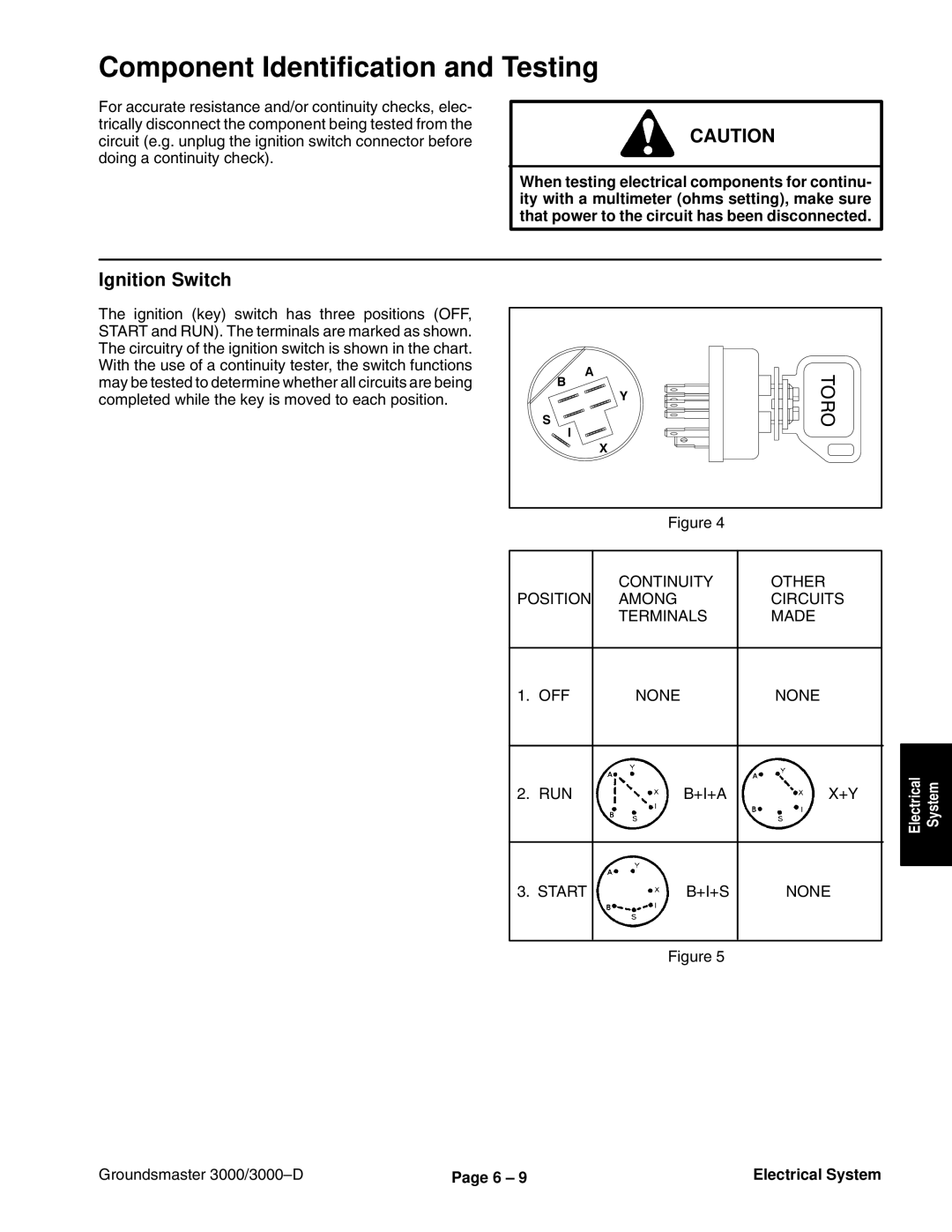
Ignition Switch
Component Identification and Testing
Diode Circuit Boards
Seat Switch
Neutral Switch
6 11 Rev. a Electrical System
Hour Meter
Hydraulic Valve Solenoids
Electrical System 6 12 Rev. a
PTO Clutch Coil
Cruise Control Coil Optional
6 13 Rev. a Electrical System
Fuel Gauge
Fuel Sender
Electrical System 6 14 Rev. a
Fuse Testing
Relay Testing
Relays and Fuses
Electrical System 6 16 Rev. a
Ampere Thermal Breaker GM 3000-D
6 17 Rev. a Electrical System
Place Testing
Live testing
Fuel Stop Solenoid GM 3000-D
Electrical System 6 18 Rev. a
Injection Advance Solenoid GM 3000-D
6 19 Rev. a Electrical System
Testing for DC Current Output Fig
Alternator GM 3000-D
Test Equipment
Electrical System 6 20 Rev. a
Temperature Sender GM 3000-D
Testing with the Engine On
Temperature Gauge GM 3000-D
Oil Pressure Switch GM 3000-D
Testing with the Engine Off
Electrical System 6 22 Rev. a
Temperature Sending Unit GM 3000-D
Glow Plugs GM 3000-D
Transport Solenoid GM 3000-D
6 23 Rev. a Electrical System
H2O in Fuel Sensor GM 3000-D
Coolant Level Sensor GM 3000-D
Disconnect connector from the sensor. Unscrew
Indicator Lights and Circuits GM 3000-D
Glow Plug Indicator Light
Ford Engine VSG-411 Electrical Component Locations GM3000
Electrical System
Personal injury or fire
Temperature Gauge GM
Thermistor GM
Handle the hot oil with extreme care to prevent
Oil Pressure Switch GM
High Temperature Switch
Anti-Dieseling Valve Solenoid GM
Indicator Lights and Circuits GM
Verify Interlock System Operation
Battery Maintenance
Caps are on tightly
Battery Service
Inspection, Maintenance, and Testing
Important Before cleaning the battery, tape or
Minimum Battery Electrolyte
Gravity Voltage
Battery Charge Specific Open Circuit
Battery
Charging
Electrical System Groundsmaster 3000/3000-D
7 1 Rev. a
2WD Rear Axle
2WD Rear Axle Groundsmaster 3000/3000-D
Rear Wheel Toe-In
7 3 Rev. a
Wheel and Tire Service
Wheel Bearing Service
Rear Axle
2WD Rear Axle Groundsmaster 3000/3000-D
8 1 Rev. a
4WD Rear Axle
4WD Rear Axle Groundsmaster 3000/3000-D
8 3 Rev. a
Change Rear Axle Lubricant
Check Rear Axle Lubricant
4WD Axle
Spindle flange
Differential shim kit
4WD Rear Axle Groundsmaster 3000/3000-D
Inch Cutting Units
Cutting Units
Specifications
Transport Latch Adjustment
Inch Cutting Units Groundsmaster 3000/3000-D
Height of Cut Adjustment
Anti-Scalp Roller Adjustment
Skid Adjustment
Bolt
Deck Pitch Adjustment
Replace Gear Box Lubricant
Check Gear Box Lubricant
Lubricate Bearings, Bushings and Gear Box
Disconnect Cutting Unit From Traction Unit
Connect Cutting Unit to Traction Unit
Drive Belt Replacement
Install Lift Arm Ball Joints
9 11 Rev. a Inch Cutting Units
Front Castor Fork Bushing Service
Castor Wheel and Bearing Service
Cutter Blade Removal and Installation
Inspecting and Sharpening Blade
Removing Spindle Housing Assembly
Blade Spindle Service
Disassembly
9 17 Rev. a Inch Cutting Units
Installing Spindle, Bearings Seals Into Spindle Housing
Correcting Cutting Unit Mismatch
Gearbox
Shaft End Play Adjustment
Drive Shaft
Inch Cutting Units Groundsmaster 3000/3000-D
10 1 Rev. C Contour 82 Cutting Unit
Contour 82I Cutting Unit
Specifications
Front Castor Wheels
Contour 82 Cutting Unit Groundsmaster 3000/3000-D
Rear Castor Wheels
Rear Deck Chain
Deck Pitch Adjustment
Grease Bearings and Bushings
Needle Valve Latch Cover
Connect Cutting Unit to Traction Unit
Castor arm tube Bushing
60 80 ft-lb 11 Kgm Castor wheel Bearing Front Caster Fork
Cutting Blade Removal and Installation
Inspecting and Sharpening Blade
Correcting Cutting Unit Mismatch
Cutting Unit Contour
Chamber Pivot Service
Contour 82 Cutting Unit 10 16 Rev. a
Inch 6 mm
Front Part Of Blade
Lift Arm Ball Joint Installation
10 19 Rev. C Contour 82 Cutting Unit
Hydraulic Motor and Blade
Contour 82 Cutting Unit 10 20 Rev. C
Passes into the center of the shaft and out to fill
Assembly
Important When greasing spindles, grease
Bearing cavity of the housing. If grease does not
Contour 82 Cutting Unit 10 22 Rev. C
Hydraulic Assembly
72I Cutting Units
Specifications
Guardian Recycler
Height of Cut Adjustment
Skid Flange nut
Gage Wheel Adjustment Rear Discharge Cutting Unit
Deck Pitch Adjustment
After 50 hours of operation
Grease Bearings, Bushings and Gear Box
Disconnect Cutting Unit From Traction Unit
11 11 Rev. a Inch Cutting Units
Gear Box Plate Capscrews & Nuts
Wavey Washer
60 80 ft-lb 8 11 Kgm Bearing Spacer
Cutter Blade Removal
Inspecting and Sharpening Blade
85 110 ft-lb 12 15 Kgm
Inch Cutting Units 11 18 Rev. a
Correcting Cutting Unit Mismatch
170 190 in-lb 196 219 Kgcm
Shaft End Play Adjustment
Drive Shaft
Electrical Diagrams
Electrical Diagrams Groundsmaster 3000/3000-D
Optional
Electrical Schematic
Start Circuits
Temp Gauge
Run Circuits
Wiring Diagram Rear Section
Gauge Hour Ignition Switch Hold SW PTO Switch Override
Wiring Diagram Front Section
Harness Drawing Rear Section
Harness Drawing Front Section
All relays and solenoids are shown as de-energized
Crank Circuits
Optional Cruise Control
Wiring Diagram Rear Section
Wiring Diagram Front Section
Switch Ground Sender
Input Power