The Grand Tour
Underside
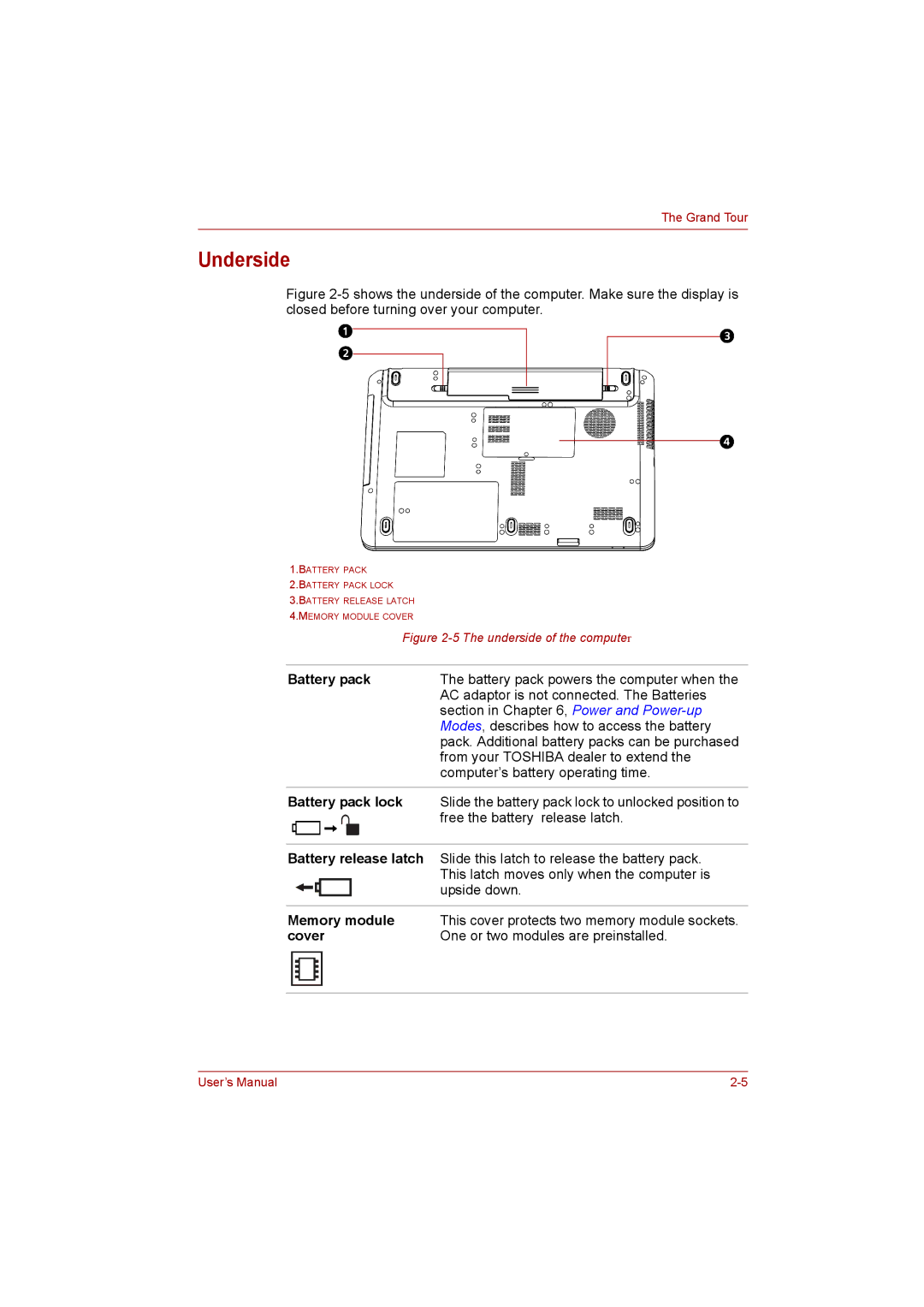
Figure 2-5 shows the underside of the computer. Make sure the display is closed before turning over your computer.
1.BATTERY PACK
2.BATTERY PACK LOCK
3.BATTERY RELEASE LATCH
4.MEMORY MODULE COVER
Figure 2-5 The underside of the computer
Battery pack | The battery pack powers the computer when the |
| AC adaptor is not connected. The Batteries |
| section in Chapter 6, Power and |
| Modes, describes how to access the battery |
| pack. Additional battery packs can be purchased |
| from your TOSHIBA dealer to extend the |
| computer’s battery operating time. |
|
|
Battery pack lock | Slide the battery pack lock to unlocked position to |
| free the battery release latch. |
|
|
Battery release latch | Slide this latch to release the battery pack. |
| This latch moves only when the computer is |
| upside down. |
|
|
Memory module | This cover protects two memory module sockets. |
cover | One or two modules are preinstalled. |
|
|
User’s Manual |
