Toshiba MR-3018 service manual Drive Circuit for Exit Motor, Drive Circuit for FAN Motor

Models: MR-3018

1 104
Download 104 pages 38.91 Kb
Page 32
Image 32

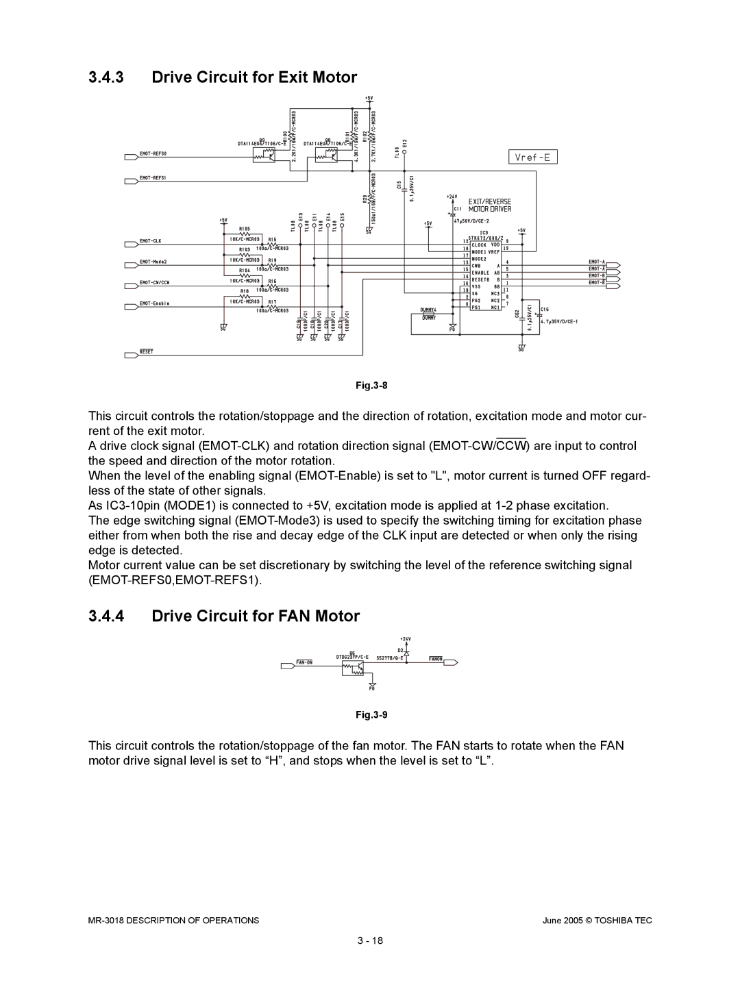
3.4.3Drive Circuit for Exit Motor

Fig.3-8

This circuit controls the rotation/stoppage and the direction of rotation, excitation mode and motor cur- rent of the exit motor.

A drive clock signal (EMOT-CLK) and rotation direction signal (EMOT-CW/CCW) are input to control the speed and direction of the motor rotation.

When the level of the enabling signal (EMOT-Enable) is set to "L", motor current is turned OFF regard- less of the state of other signals.

As IC3-10pin (MODE1) is connected to +5V, excitation mode is applied at 1-2 phase excitation.

The edge switching signal (EMOT-Mode3) is used to specify the switching timing for excitation phase either from when both the rise and decay edge of the CLK input are detected or when only the rising edge is detected.

Motor current value can be set discretionary by switching the level of the reference switching signal (EMOT-REFS0,EMOT-REFS1).

3.4.4Drive Circuit for FAN Motor

Fig.3-9

This circuit controls the rotation/stoppage of the fan motor. The FAN starts to rotate when the FAN motor drive signal level is set to “H”, and stops when the level is set to “L”.

MR-3018 DESCRIPTION OF OPERATIONS

June 2005 © TOSHIBA TEC

3 - 18

Page 32
Image 32
Toshiba MR-3018 service manual Drive Circuit for Exit Motor, Drive Circuit for FAN Motor