Replacement Procedures
4.12 Cover assembly
Removing the cover assembly
The following describes the procedure for removing the cover assembly (See Figure
1.Turn over the computer.
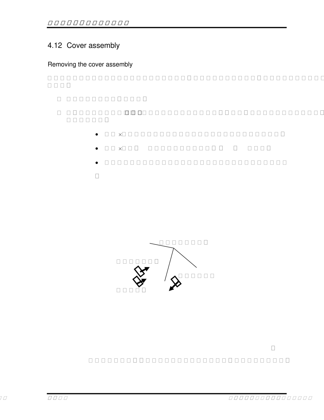
2.Remove the following screws securing the cover assembly from the back and bottom of computer.
• | M2.5⋅6.0 | FLAT BIND screw Front | x3 |
• | M2.5⋅6.0B | FLAT BIND screw Back | x18 |
• | M2.5x4.0 | FLAT BIND screw | x1 |
Front 2.5*6 x3
Touchpad FFC
Fingerprint
Top LENS
Figure 4-19 Removing the screws cable from connect (front)
Satellite P100 Maintenance Manual |