Replacement Procedures
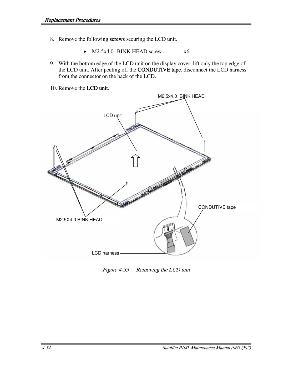
8. Remove the following screws securing the LCD unit.
• M2.5x4.0 BINK HEAD screw | x6 |
9.With the bottom edge of the LCD unit on the display cover, lift only the top edge of the LCD unit. After peeling off the CONDUTIVE tape, disconnect the LCD harness from the connector on the back of the LCD.
10.Remove the LCD unit.
M2.5x4.0 BINK HEAD
LCD unit
CONDUTIVE tape
M2.5X4.0 BINK HEAD
LCD harness
Figure 4-33 Removing the LCD unit
Satellite P100 Maintenance Manual |