Chapter 4 Replacement Procedures
Figure 4-8-2 Remove the memory slot cover
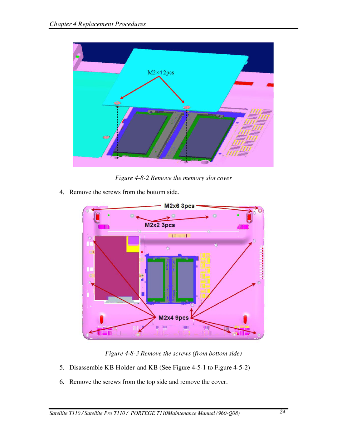
4. Remove the screws from the bottom side.
Figure 4-8-3 Remove the screws (from bottom side)
5.Disassemble KB Holder and KB (See Figure
6.Remove the screws from the top side and remove the cover.
Satellite T110 / Satellite Pro T110 / PORTEGE T110Maintenance Manual | 24 |