Board Layout
B.3 CRT Board
<Front layout>
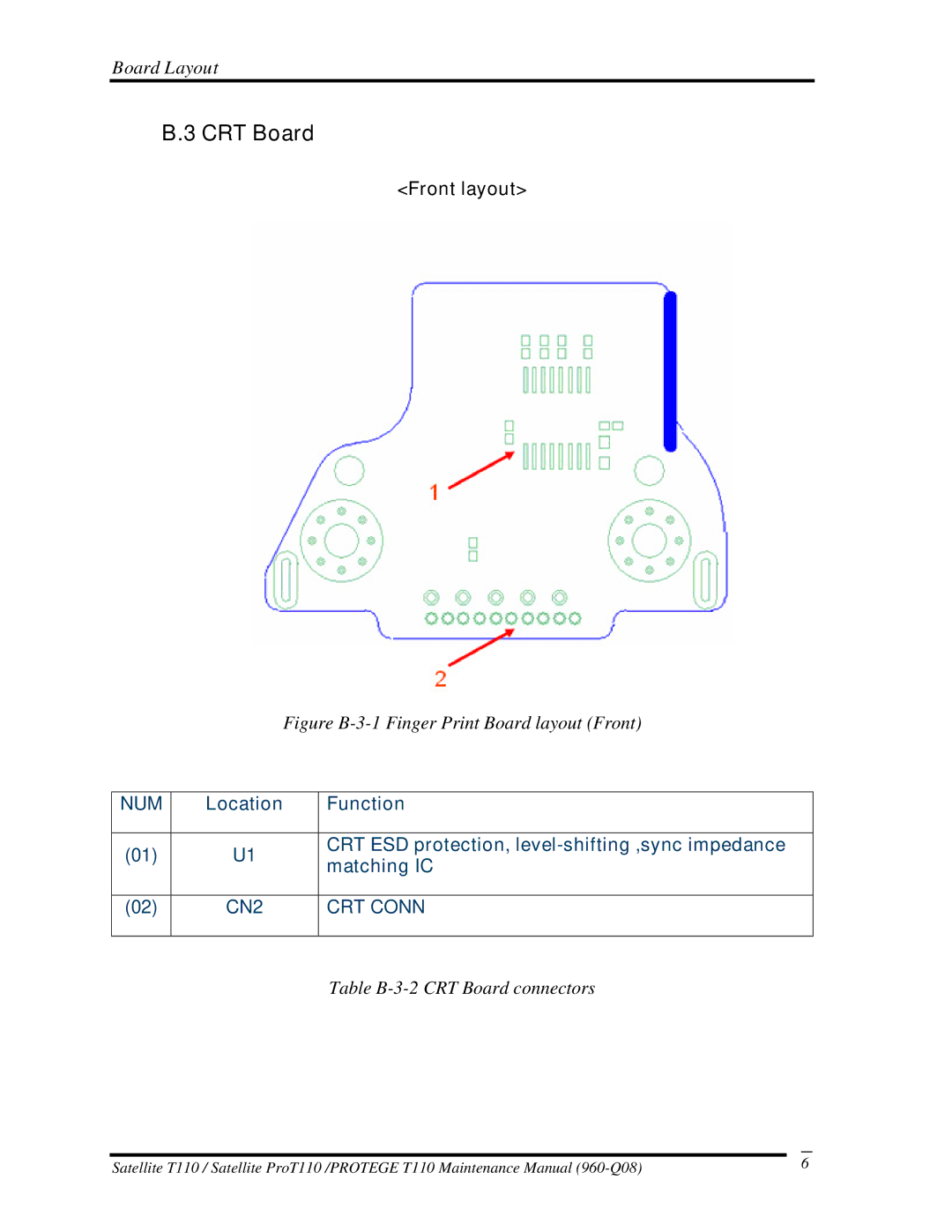
Figure B-3-1 Finger Print Board layout (Front)
NUM | Location | Function | |
|
|
| |
(01) | U1 | CRT ESD protection, | |
matching IC | |||
|
| ||
|
|
| |
(02) | CN2 | CRT CONN | |
|
|
|
Table
Satellite T110 / Satellite ProT110 /PROTEGE T110 Maintenance Manual |
| 6 |
