Chapter 4 Replacement Procedures
Figure 4-8-4 Remove the screws (from top side)
7.Disconnect the touch pad FFC/LAN FFC/Power FFC from the connector on the system board.
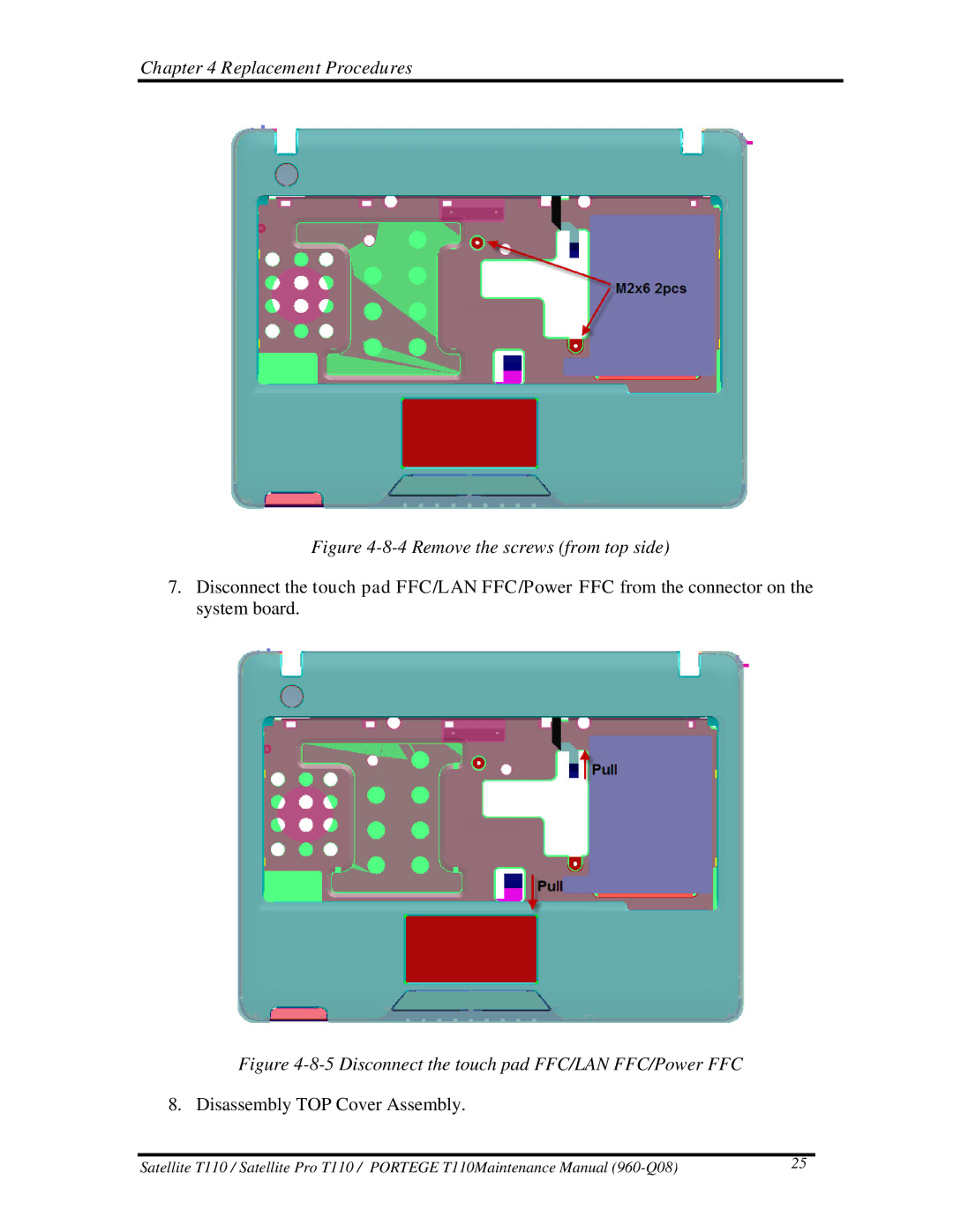
Figure 4-8-5 Disconnect the touch pad FFC/LAN FFC/Power FFC
8. Disassembly TOP Cover Assembly.
Satellite T110 / Satellite Pro T110 / PORTEGE T110Maintenance Manual | 25 |