|
|
|
|
|
|
|
| Table | |
|
|
|
|
|
|
|
|
| |
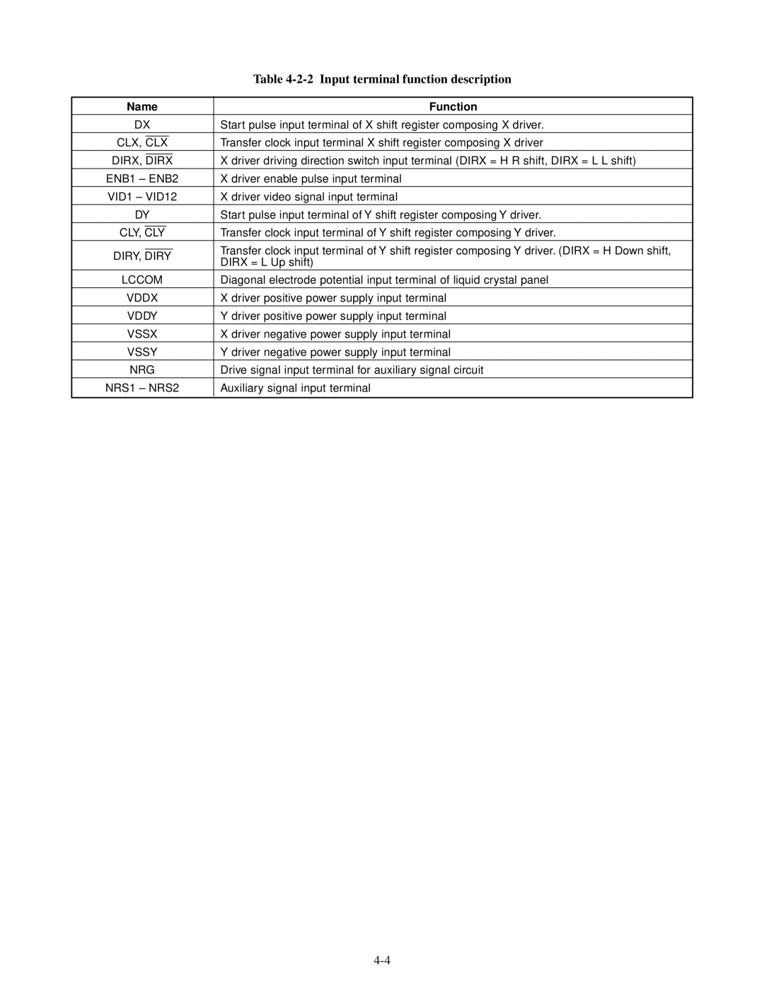
Name | Function | ||||||||
DX | Start pulse input terminal of X shift register composing X driver. | ||||||||
|
|
|
|
|
|
| |||
CLX, | CLX |
|
|
| Transfer clock input terminal X shift register composing X driver | ||||
|
|
|
|
| |||||
DIRX, | DIRX |
|
| X driver driving direction switch input terminal (DIRX = H R shift, DIRX = L L shift) | |||||
ENB1 – ENB2 | X driver enable pulse input terminal | ||||||||
VID1 – VID12 | X driver video signal input terminal | ||||||||
|
|
|
|
|
|
|
|
| |
DY | Start pulse input terminal of Y shift register composing Y driver. | ||||||||
|
|
|
| ||||||
CLY, | CLY |
|
| Transfer clock input terminal of Y shift register composing Y driver. | |||||
|
|
|
|
|
|
|
| Transfer clock input terminal of Y shift register composing Y driver. (DIRX = H Down shift, | |
DIRY, DIRY | |||||||||
DIRX = L Up shift) | |||||||||
|
|
|
|
|
|
|
| ||
LCCOM | Diagonal electrode potential input terminal of liquid crystal panel | ||||||||
VDDX | X driver positive power supply input terminal | ||||||||
VDDY | Y driver positive power supply input terminal | ||||||||
VSSX | X driver negative power supply input terminal | ||||||||
VSSY | Y driver negative power supply input terminal | ||||||||
NRG | Drive signal input terminal for auxiliary signal circuit | ||||||||
NRS1 – NRS2 | Auxiliary signal input terminal | ||||||||
|
|
|
|
|
|
|
|
| |
Page 11
Image 11