CI005 and CI006 are capacitors to stabilize the fluores- cent lamp discharging current. After the discharging starts, CI005 and CI006 limit the flow of the current with the reactance (XC = 1/wc) of CI005 and CI006.
Before the fluorescent lamp turns on, the collector pulse of QI007 is 70 – 80
ARM SW works as a ON/OFF switch for the camera power supply. When ARM SW turns on, the power is supplied to the camera.
The waveforms of each section at operation is shown in Figs.
9-2. Troubleshooting
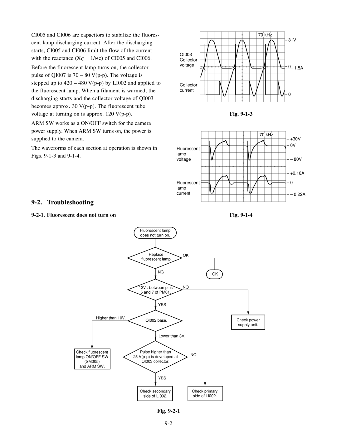
9-2-1. Fluorescent does not turn on
QI003 Collector voltage
Collector current
Fluorescent lamp voltage
Fluorescent lamp current
70![]() kHz
kHz
31V
0 | 1.5A |
0
Fig.
70 kHz
+30V
0V
– 80V
+0.16A
0
– 0.22A
Fig.
Fluorescent lamp does not turn on.
|
|
| Replace | OK | ||||||
|
|
| fluorescent lamp. |
|
|
|
|
|
| |
|
|
|
| NG |
|
|
|
|
|
|
|
|
|
|
|
| OK | ||||
|
|
|
|
|
|
| ||||
|
|
| 12V : between pins | NO | ||||||
|
|
| 5 and 7 of PM01. |
|
|
|
|
|
| |
|
|
|
| YES |
|
|
|
|
|
|
| Higher than 10V. |
|
|
|
|
|
|
|
| |
|
|
|
|
|
|
|
|
| ||
| QI002 base. |
|
|
|
| Check power | ||||
|
|
|
|
|
|
|
|
| supply unit. | |
|
|
|
|
|
|
|
|
|
| |
|
|
|
| Lower than 3V. | ||||||
|
| Pulse higher than |
|
|
|
|
|
| ||
Check fluorescent |
|
| NO | |||||||
lamp ON/OFF SW |
| 25 |
| |||||||
|
|
|
|
|
|
| ||||
(SM005) |
| QI003 collector. |
|
|
|
|
|
| ||
and ARM SW. |
|
|
|
|
|
|
|
|
| |
|
|
|
| YES |
|
|
|
|
|
|
|
|
|
|
|
|
|
|
|
|
|
Check secondary
side of LI002.
Check primary side of LI002.
Fig.