7-2. Input Signal Switch Section
The signal SW section works as a circuit to supply the signal to the signal process section in the next stage and each output terminal by switching the signal entered (video, audio).
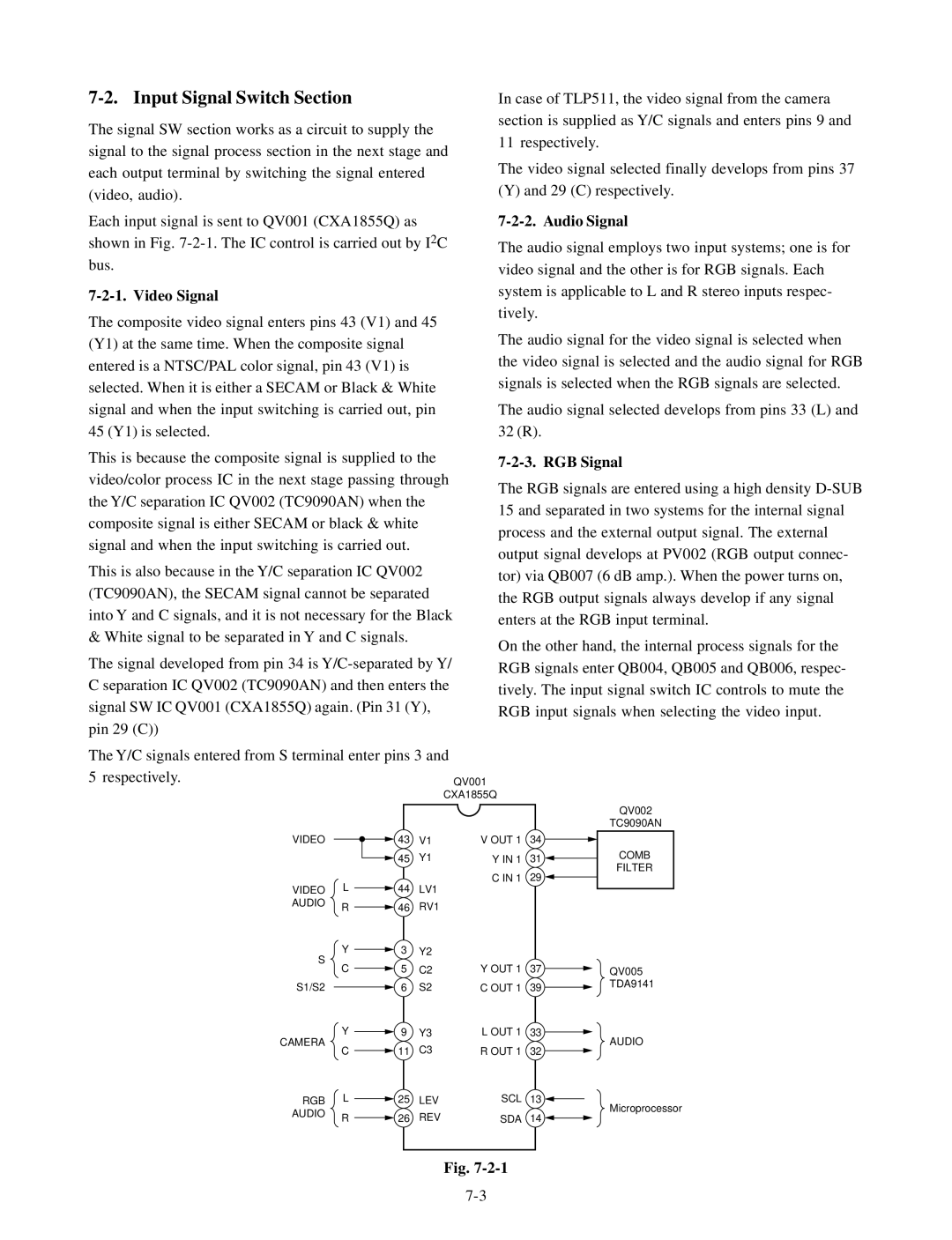
Each input signal is sent to QV001 (CXA1855Q) as shown in Fig.
7-2-1. Video Signal
The composite video signal enters pins 43 (V1) and 45 (Y1) at the same time. When the composite signal entered is a NTSC/PAL color signal, pin 43 (V1) is selected. When it is either a SECAM or Black & White signal and when the input switching is carried out, pin 45 (Y1) is selected.
This is because the composite signal is supplied to the video/color process IC in the next stage passing through the Y/C separation IC QV002 (TC9090AN) when the composite signal is either SECAM or black & white signal and when the input switching is carried out.
This is also because in the Y/C separation IC QV002 (TC9090AN), the SECAM signal cannot be separated into Y and C signals, and it is not necessary for the Black & White signal to be separated in Y and C signals.
The signal developed from pin 34 is
The Y/C signals entered from S terminal enter pins 3 and 5 respectively.
VIDEO ![]() 43 V1
43 V1
![]() 45 Y1
45 Y1
VIDEO L | 44 | LV1 | ||
AUDIO | R | 46 | RV1 | |
| ||||
S | Y | 3 | Y2 | |
C | 5 | C2 | ||
| ||||
S1/S2 |
| 6 | S2 | |
In case of TLP511, the video signal from the camera section is supplied as Y/C signals and enters pins 9 and 11 respectively.
The video signal selected finally develops from pins 37
(Y) and 29 (C) respectively.
7-2-2. Audio Signal
The audio signal employs two input systems; one is for video signal and the other is for RGB signals. Each system is applicable to L and R stereo inputs respec- tively.
The audio signal for the video signal is selected when the video signal is selected and the audio signal for RGB signals is selected when the RGB signals are selected.
The audio signal selected develops from pins 33 (L) and 32 (R).
7-2-3. RGB Signal
The RGB signals are entered using a high density
On the other hand, the internal process signals for the RGB signals enter QB004, QB005 and QB006, respec- tively. The input signal switch IC controls to mute the RGB input signals when selecting the video input.
|
|
|
|
| QV002 |
|
|
|
|
| TC9090AN |
V OUT 1 | 34 |
|
|
| COMB |
|
|
| |||
Y IN 1 | 31 |
|
|
| |
|
|
| |||
|
|
| FILTER | ||
C IN 1 | 29 |
|
|
| |
|
|
|
| ||
|
|
|
| ||
|
|
|
|
|
|
Y OUT 1 | 37 | QV005 |
C OUT 1 | 39 | TDA9141 |
|
CAMERA
Y ![]() 9 Y3
9 Y3
C ![]() 11 C3
11 C3
L OUT 1 33 ![]()
AUDIO
R OUT 1 32 ![]()
RGB | L | 25 | LEV |
AUDIO | R | 26 | REV |
|
SCL | 13 |
| Microprocessor |
SDA | 14 |
Fig.