4. R.G.B. DRIVE CIRCUIT
4-1. Outline
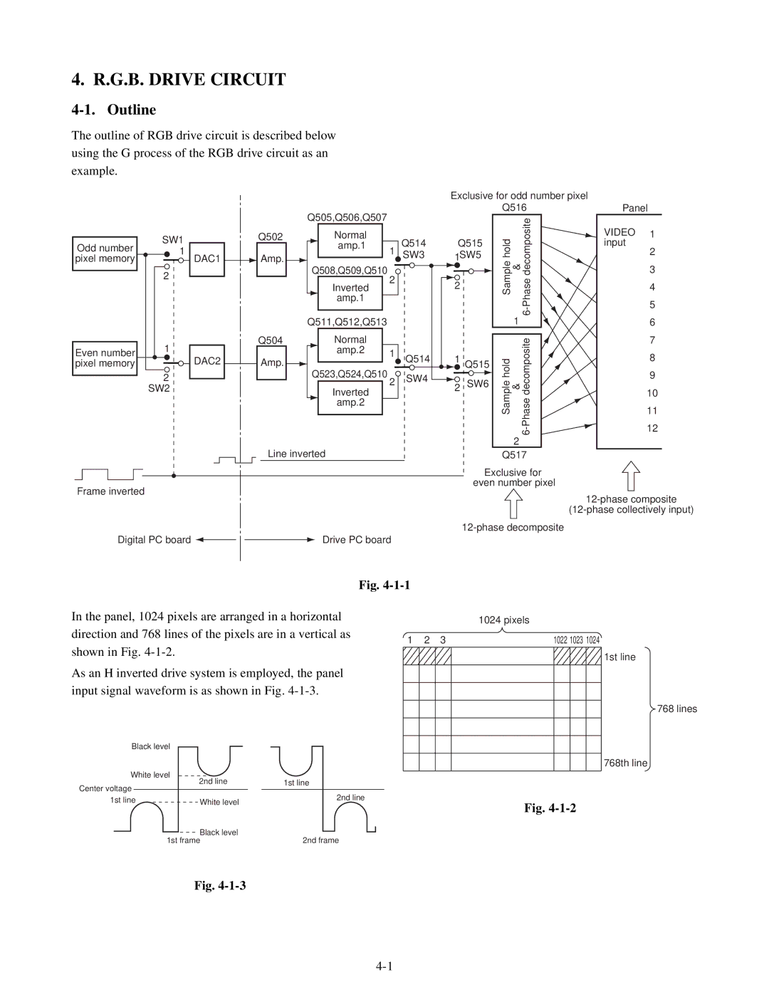
The outline of RGB drive circuit is described below
using the G process of the RGB drive circuit as an
example.
Odd number pixel memory
Even number pixel memory
SW1
1
DAC1
2
1
![]() DAC2
DAC2
2
SW2
| Q505,Q506,Q507 |
|
|
Q502 | Normal |
| Q514 |
| amp.1 | 1 | |
Amp. |
| SW3 | |
|
|
| |
| Q508,Q509,Q510 | 2 |
|
| Inverted |
| |
|
|
| |
| amp.1 |
|
|
| Q511,Q512,Q513 |
|
|
Q504 | Normal |
|
|
| amp.2 | 1 | Q514 |
Amp. |
| ||
|
| ||
Q523,Q524,Q510 |
|
| |
| 2 | SW4 | |
|
| ||
| Inverted |
| |
|
|
| |
| amp.2 |
|
|
Exclusive for odd number pixel |
| ||||
| Q516 | Panel | |||
Q515 |
|
| VIDEO 1 | ||
Sample hold |
| input | |||
1SW5 |
| 2 | |||
& |
| ||||
| 3 | ||||
2 | 4 | ||||
| 5 | ||||
|
| 1 | 6 | 6 | |
|
|
| |||
|
|
| Phase decomposite | 7 | |
1 Q515 | Sample hold |
| 8 | ||
| 9 | ||||
2 SW6 | & | ||||
10 | |||||
| |||||
| 11 | ||||
| 12 | ||||
|
|
| - | ||
|
|
| 6 | ||
|
| 2 |
|
| |
Line inverted
Frame inverted
Digital PC board |
| Drive PC board |
|
Q517 |
Exclusive for |
even number pixel |
Fig.
In the panel, 1024 pixels are arranged in a horizontal direction and 768 lines of the pixels are in a vertical as shown in Fig.
As an H inverted drive system is employed, the panel input signal waveform is as shown in Fig.
Black level |
|
|
| |
White level | 2nd line |
| 1st line | |
Center voltage |
|
| ||
|
|
|
| |
|
|
| 2nd line | |
1st line | White level |
| ||
|
| |||
|
| Black level |
|
|
| 1st frame |
| 2nd frame | |
1024 pixels
1 | 2 | 3 | 1022 1023 1024 |
1st line
768 lines
768th line
Fig.
Fig.