5-14. Applicable Signal
Various kinds of signals are used as the applicable signals in the preset mode (standard value) as shown in Table
In the preset modes, the applicable signals are based on the VESA standard, so the sample frequency (CLOCK adjustment in the panel menu) is not used, but the adjustment is allowed only in the user mode.
In other mode, the signal line number is detected to allow the separate adjustment in the VGA system (basically effective for line number of 480 lines), SVGA system (basically effective for line number of 600 lines) and XGA system (basically effective for line number of 768 lines).
In the user mode of SGA system (900 line system and 1024 line system), the input signal is applicable to the plain display mode. That is, the signal is displayed in different two ways owing to the line number in vertical direction.
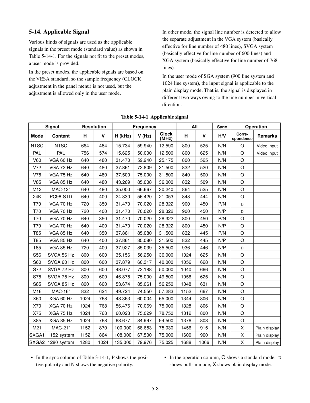
Table 5-14-1 Applicable signal
| Signal | Resolution | Frequency |
|
| All | Sync | Operation | |||||
Mode | Content | H | V | H (kHz) | V (Hz) |
| Clock | H |
| V | H/V | Corre- | Remarks |
| (MHz) |
| spondence | ||||||||||
|
|
|
|
|
|
|
|
|
|
|
| ||
NTSC | NTSC | 664 | 484 | 15.734 | 59.940 |
| 12.590 | 800 |
| 525 | N/N | O | Video input |
PAL | PAL | 756 | 574 | 15.625 | 50.000 |
| 12.500 | 800 |
| 625 | N/N | O | Video input |
V60 | VGA 60 Hz | 640 | 480 | 31.470 | 59.940 |
| 25.175 | 800 |
| 525 | N/N | O |
|
V72 | VGA 72 Hz | 640 | 480 | 37.861 | 72.809 |
| 31,500 | 832 |
| 520 | N/N | O |
|
V75 | VGA 75 Hz | 640 | 480 | 37.500 | 75.000 |
| 31.500 | 840 |
| 500 | N/N | O |
|
V85 | VGA 85 Hz | 640 | 480 | 43.269 | 85.008 |
| 36.000 | 832 |
| 509 | N/N | O |
|
M13 | 640 | 480 | 35.000 | 66.667 |
| 30.240 | 864 |
| 525 | N/N | O |
| |
24K |
| 640 | 400 | 24.830 | 56.420 |
| 21.053 | 848 |
| 444 | N/N | O |
|
T70 | VGA 70 Hz | 720 | 350 | 31.470 | 70.020 |
| 28.322 | 900 |
| 450 | P/N | D |
|
T70 | VGA 70 Hz | 720 | 400 | 31.470 | 70.020 |
| 28.322 | 900 |
| 450 | N/P | D |
|
T70 | VGA 70 Hz | 640 | 350 | 31.470 | 70.020 |
| 28.322 | 800 |
| 450 | P/N | O |
|
T70 | VGA 70 Hz | 640 | 400 | 31.470 | 70.020 |
| 28.322 | 800 |
| 450 | N/P | O |
|
T85 | VGA 85 Hz | 640 | 350 | 37.861 | 85.080 |
| 31.500 | 832 |
| 445 | P/N | O |
|
T85 | VGA 85 Hz | 640 | 400 | 37.861 | 85.080 |
| 31.500 | 832 |
| 445 | N/P | O |
|
T85 | VGA 85 Hz | 720 | 400 | 37.927 | 85.039 |
| 35.500 | 936 |
| 446 | N/P | D |
|
S56 | SVGA 56 Hz | 800 | 600 | 35.156 | 56.250 |
| 36.000 | 1024 |
| 625 | N/N | O |
|
S60 | SVGA 60 Hz | 800 | 600 | 37.879 | 60.317 |
| 40.000 | 1056 |
| 628 | N/N | O |
|
|
|
|
|
|
|
|
|
|
|
|
|
|
|
S72 | SVGA 72 Hz | 800 | 600 | 48.077 | 72.188 |
| 50.000 | 1040 |
| 666 | N/N | O |
|
S75 | SVGA 75 Hz | 800 | 600 | 46.875 | 75.000 |
| 49.500 | 1056 |
| 625 | N/N | O |
|
S85 | SVGA 85 Hz | 800 | 600 | 53.674 | 85.061 |
| 56.250 | 1048 |
| 631 | N/N | O |
|
M16 | 832 | 624 | 49.724 | 74.550 |
| 57.283 | 1152 |
| 667 | N/N | O |
| |
X60 | XGA 60 Hz | 1024 | 768 | 48.363 | 60.004 |
| 65.000 | 1344 |
| 806 | N/N | O |
|
X70 | XGA 70 Hz | 1024 | 768 | 56.476 | 70.069 |
| 75.000 | 1328 |
| 806 | N/N | O |
|
X75 | XGA 75 Hz | 1024 | 768 | 60.023 | 75.029 |
| 78.750 | 1312 |
| 800 | N/N | O |
|
X85 | XGA 85 Hz | 1024 | 768 | 68.677 | 84.997 |
| 94.500 | 1376 |
| 808 | N/N | O |
|
M21 | 1152 | 870 | 100.000 | 68.653 |
| 75.030 | 1456 |
| 915 | N/N | X | Plain display | |
SXGA1 | 1152 system | 1152 | 864 | 108.000 | 67.500 |
| 75.000 | 1600 |
| 900 | N/N | X | Plain display |
|
|
|
|
|
|
|
|
|
|
|
|
|
|
SXGA2 | 1280 system | 1280 | 1024 | 135.000 | 79.976 |
| 75.025 | 1688 |
| 1066 | N/N | X | Plain display |
• In the sync column of Table | • In the operation column, O shows a standard mode, D | ||||||||||||
tive polarity and N shows the negative polarity. |
|
| shows | ||||||||||