5-3. Power Supply Reset Process
In the power supply reset process, power supply reset IC (RN5VD27A), QL004 is employed.
The reset IC,QL004, develops the reset signal when the power supply voltage for the microprocessor varies and becomes lower than the specified voltage, and sends the signal to the reset terminal of the system microprocessor (QL002).
5-4. Non-volatile Memory Control Process
In the
When the power (AC) is on, all the adjustment data are read out by the system microprocessor (QL002), then the previous status is realized.
When saving the data, all the adjustment data are written by the system microprocessor (QL002), then the current status is preserved.
However, if a failure (such as power interruption due to lightning, etc.) occurs during the adjustment data writing, a data error may occur. If the data is determined as incorrect, the initial data memorized on the system microprocessor (QL002) is read out and stored on the
5-5. Remote Control Reception Process
In the remote control reception process, a remote control unit
The remote control signals for rear panel and camera section (for TLP511) are selected by QL012 buffer (TC74HC125AF). Then both signals are mixed with the remote control signal for front panel through QL005 buffer (74HC14AF).
Finally, the signal mixed is supplied to the remote control terminal of the system microprocessor (QL002).
5-6. RS-232C Transmission/Reception Process
In the
In the
|
|
|
|
|
|
|
| |||
|
|
|
|
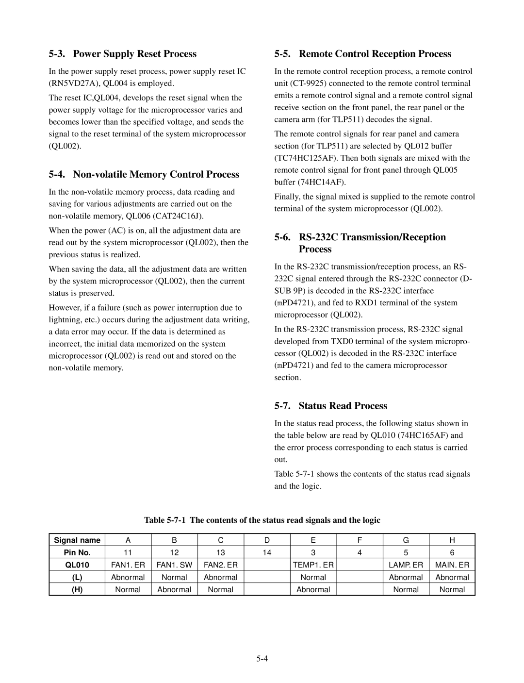
| In the status read process, the following status shown in | |||||
|
|
|
|
| the table below are read by QL010 (74HC165AF) and | |||||
|
|
|
|
| the error process corresponding to each status is carried | |||||
|
|
|
|
| out. |
|
|
|
| |
|
|
|
|
| Table | |||||
|
|
|
|
| and the logic. |
|
|
|
| |
| Table |
|
| |||||||
|
|
|
|
|
|
|
|
|
|
|
Signal name | A | B | C | D |
| E | F |
| G | H |
Pin No. | 11 | 12 | 13 | 14 |
| 3 | 4 |
| 5 | 6 |
QL010 | FAN1. ER | FAN1. SW | FAN2. ER |
|
| TEMP1. ER |
|
| LAMP. ER | MAIN. ER |
(L) | Abnormal | Normal | Abnormal |
|
| Normal |
|
| Abnormal | Abnormal |
(H) | Normal | Abnormal | Normal |
|
| Abnormal |
|
| Normal | Normal |
|
|
|
|
|
|
|
|
|
|
|