3. OPTICAL SYSTEM
3-1. Configuration
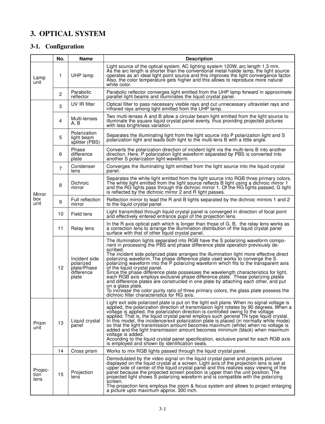
| No. | Name | Description | |
|
|
| Light source of the optical system. AC lighting system 120W, arc length 1.3 mm. | |
| 1 | UHP lamp | As the arc length is shorter than the conventional metal halide lamp, the light source | |
Lamp | operates as an ideal light point source and this improves the light convergence factor. | |||
|
| Also, the color temperature gets higher and this allows to reproduce more natural | ||
unit |
|
| ||
|
| white color. | ||
|
|
| ||
| 2 | Parabolic | Parabolic reflector converges light emitted from the UHP lamp forward in approximate | |
| reflector | parallel light beams and illuminates the liquid crystal panel. | ||
|
| |||
| 3 | UV IR filter | Optical filter to pass necessary visible rays and cut unnecessary ultraviolet rays and | |
|
| infrared rays among light emitted from the UHP lamp. | ||
|
|
| ||
| 4 | Two | ||
| illuminate the square liquid crystal panel evenly, thus providing projected pictures | |||
| A, B | |||
|
| with less brightness variation. | ||
|
|
| ||
| 5 | Polarization | Separates the illuminating light from the light source into P polarization light and S | |
| light beam | |||
| polarization light and leads both light to the | |||
|
| splitter (PBS) | ||
|
|
| ||
| 6 | Phase | Converts the polarization direction of incident light via the | |
| difference | direction. Here, P polarization light waveform separated by PBS is converted into | ||
|
| plate | another S polarization light waveform. | |
| 7 | Condenser | Converges the illuminating light emitted from the light source into the liquid crystal | |
| lens | panel. | ||
|
| |||
|
| Dichroic | Separates the white light emitted from the light source into RGB three primary colors. | |
| 8 | The white light emitted from the light source reflects B light using a dichroic mirror 1 | ||
| mirror | and the RG lights pass through the dichroic mirror 1. Of the RG lights passed, G light | ||
|
| |||
Mirror |
|
| is reflected by the dichroic mirror 2 and R light passes. | |
box | 9 | Full reflection | Reflection mirror to lead the R and B lights separated by the dichroic mirrors 1 and 2 | |
unit | mirror | to the liquid crystal panel. | ||
| ||||
| 10 | Field lens | Light transmitted through liquid crystal panel is converged in direction of focal point | |
| and effectively entered entrance pupil of the projection lens. | |||
|
|
| ||
|
|
| In the R axis optical path which is longer than those of G, B, the relay lens works as | |
| 11 | Relay lens | a correction lens to arrange the illumination distribution of the liquid crystal panel | |
|
|
| surface with that of other liquid crystal panel. | |
|
|
| The illumination lights separated into RGB have the S polarizing waveform compo- | |
|
|
| nent in processing the PBS and phase difference plate operation previously de- | |
|
|
| scribed. | |
|
| Incident side | The incident side polarized plate arranges the illumination light more effective direct | |
|
| polarizing waveform. The phase difference plate used works to converge the S | ||
| 12 | polarized | polarizing waveform into the P polarizing waveform which fits to the transparent axis | |
| plate/Phase | of the liquid crystal panel. | ||
|
| difference | Since the phase difference plate possesses the wavelength characteristics for light, | |
|
| plate | each RGB axis employs exclusive phase difference plate. These polarizing plates | |
|
|
| and difference plates are constructed in one plate by attaching each other, and put | |
|
|
| on a glass plate. | |
|
|
| To increase the color purity ratio of three primary colors, the glass plate possess the | |
|
|
| dichroic filter characteristics for RG axis. | |
|
|
| Light exit side polarized plate is put on the light exit plane. When no signal voltage is | |
|
|
| applied, the polarization direction of transmission light rotates by 90 degrees. When a | |
|
|
| voltage is applied, the polarization direction is controlled owing to the voltage | |
|
| Liquid crystal | applied. That is, the liquid crystal panel employs such general TN type liquid crystal. | |
Prism | 13 | In this model, the incidence/exit polarization plate is placed (in normally white mode) | ||
panel | so that the light transmission amount becomes maximum (white) when no voltage is | |||
unit |
| |||
|
| added and the light transmission amount becomes minimum (black) when maximum | ||
|
|
| ||
|
|
| voltage is added. | |
|
|
| According to the liquid crystal panel specification, exclusive panel for each RGB axis | |
|
|
| is employed and shown by identification seals. | |
| 14 | Cross prism | Works to mix RGB lights passed through the liquid crystal panel. | |
|
|
| Demodulated by the video signal on the liquid crystal panel and projects pictures | |
|
|
| displayed on the liquid crystal at a screen. Light axis of the projection lens is set at | |
Projec- |
| Projection | upper side of center of the liquid crystal panel and this realizes easy viewing of the | |
15 | panel because the projected screen position is upper than the unit position. The | |||
tion | ||||
lens | projected light shows S polarizing waveform and is compatible with the polarizing | |||
lens |
| |||
|
| screen. | ||
|
|
| ||
|
|
| The projection lens employs the zoom & focus system and allows to project enlarging | |
|
|
| a picture upto maximum approx. 300 inch. | |
|
|
|
|