2.LAMP POWER SUPPLY CIRCUIT (LAMP DRIVER)
2-1. Configuration
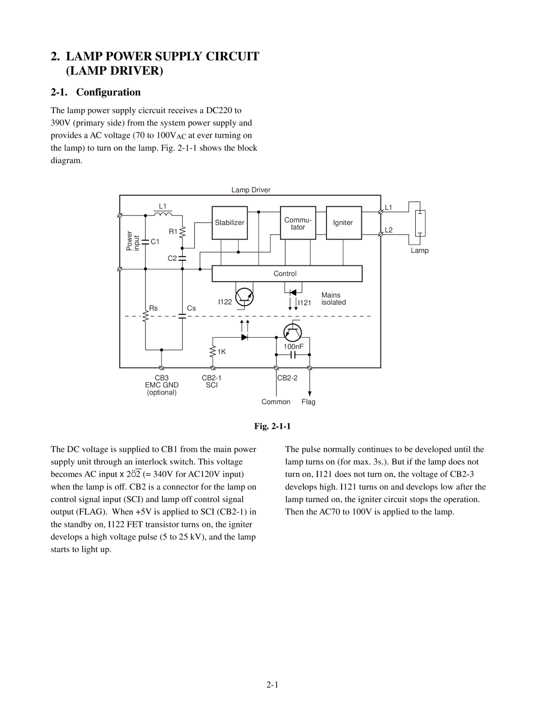
The lamp power supply cicrcuit receives a DC220 to 390V (primary side) from the system power supply and provides a AC voltage (70 to 100VAC at ever turning on the lamp) to turn on the lamp. Fig.
|
| Lamp Driver |
|
| |
| L1 |
|
|
| L1 |
|
| Stabilizer | Commu- | Igniter | |
|
| tator | |||
Power input | R1 |
| L2 | ||
|
|
| |||
C1 |
|
|
|
| |
|
|
|
|
| |
| C2 |
|
|
| Lamp |
|
|
|
|
| |
|
|
| Control |
|
|
|
| I122 |
|
| Mains |
| Rs |
| I121 | isolated | |
| Cs |
|
|
| |
|
| 1K | 100nF |
| |
|
|
|
|
| |
| CB3 |
|
| ||
| EMC GND | SCI |
|
|
|
| (optional) |
|
|
|
|
|
|
| Common | Flag |
|
Fig.
The DC voltage is supplied to CB1 from the main power supply unit through an interlock switch. This voltage
becomes AC input x 2Ö2 (= 340V for AC120V input) when the lamp is off. CB2 is a connector for the lamp on control signal input (SCI) and lamp off control signal output (FLAG). When +5V is applied to SCI
The pulse normally continues to be developed until the lamp turns on (for max. 3s.). But if the lamp does not turn on, I121 does not turn on, the voltage of