7-5. Microprocessor Interface
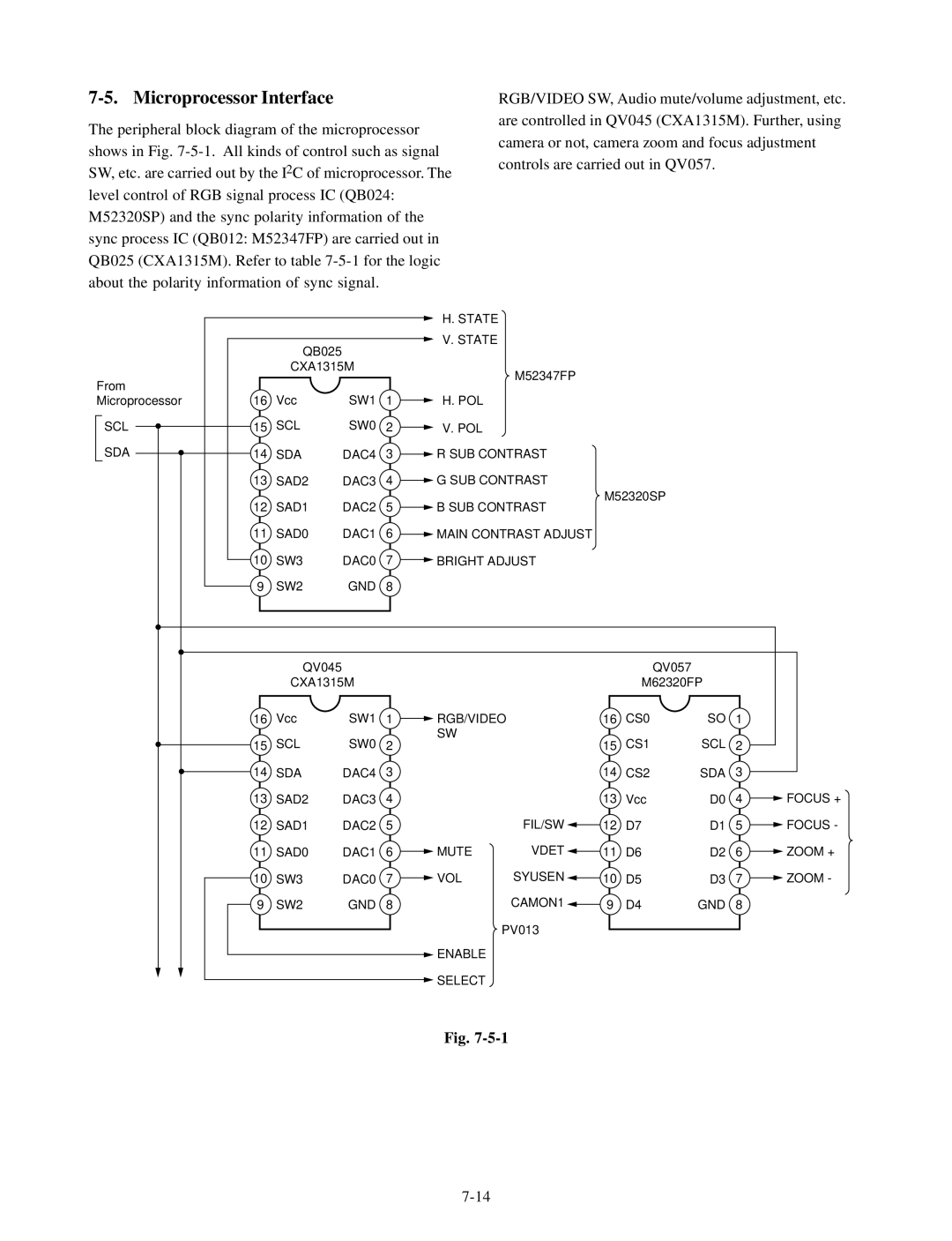
The peripheral block diagram of the microprocessor shows in Fig.
RGB/VIDEO SW, Audio mute/volume adjustment, etc. are controlled in QV045 (CXA1315M). Further, using camera or not, camera zoom and focus adjustment controls are carried out in QV057.
|
|
|
|
| H. STATE |
|
| QB025 |
|
| V. STATE |
|
|
|
|
| |
|
| CXA1315M |
| M52347FP | |
From |
|
|
|
| |
|
|
|
|
| |
Microprocessor | 16 | Vcc | SW1 | 1 | H. POL |
SCL | 15 | SCL | SW0 | 2 | V. POL |
SDA | 14 | SDA | DAC4 | 3 | R SUB CONTRAST |
| 13 | SAD2 | DAC3 | 4 | G SUB CONTRAST |
| 12 | SAD1 | DAC2 | 5 | M52320SP |
| B SUB CONTRAST | ||||
| 11 | SAD0 | DAC1 | 6 | MAIN CONTRAST ADJUST |
| 10 | SW3 | DAC0 | 7 | BRIGHT ADJUST |
| 9 | SW2 | GND | 8 |
|
| QV045 |
|
|
|
|
|
| QV057 |
|
|
| CXA1315M |
|
|
|
| M62320FP |
|
| ||
16 | Vcc | SW1 | 1 | RGB/VIDEO | 16 | CS0 | SO | 1 |
| |
15 | SCL | SW0 | 2 | SW |
| 15 | CS1 | SCL | 2 |
|
|
|
| ||||||||
14 | SDA | DAC4 | 3 |
|
| 14 | CS2 | SDA | 3 |
|
13 | SAD2 | DAC3 | 4 |
|
| 13 | Vcc | D0 | 4 | FOCUS + |
12 | SAD1 | DAC2 | 5 |
| FIL/SW | 12 | D7 | D1 | 5 | FOCUS - |
11 | SAD0 | DAC1 | 6 | MUTE | VDET | 11 | D6 | D2 | 6 | ZOOM + |
10 | SW3 | DAC0 | 7 | VOL | SYUSEN | 10 | D5 | D3 | 7 | ZOOM - |
9 | SW2 | GND | 8 |
| CAMON1 | 9 | D4 | GND | 8 |
|
|
|
|
|
| PV013 |
|
|
|
|
|
|
|
|
| ENABLE |
|
|
|
|
|
|
|
|
|
| SELECT |
|
|
|
|
|
|
Fig.