5-2. System Microprocessor
The system microprocessor QL002 employs an 8 bit
In this system microprocessor, a program area is pro- vided inside the
Using an exclusive
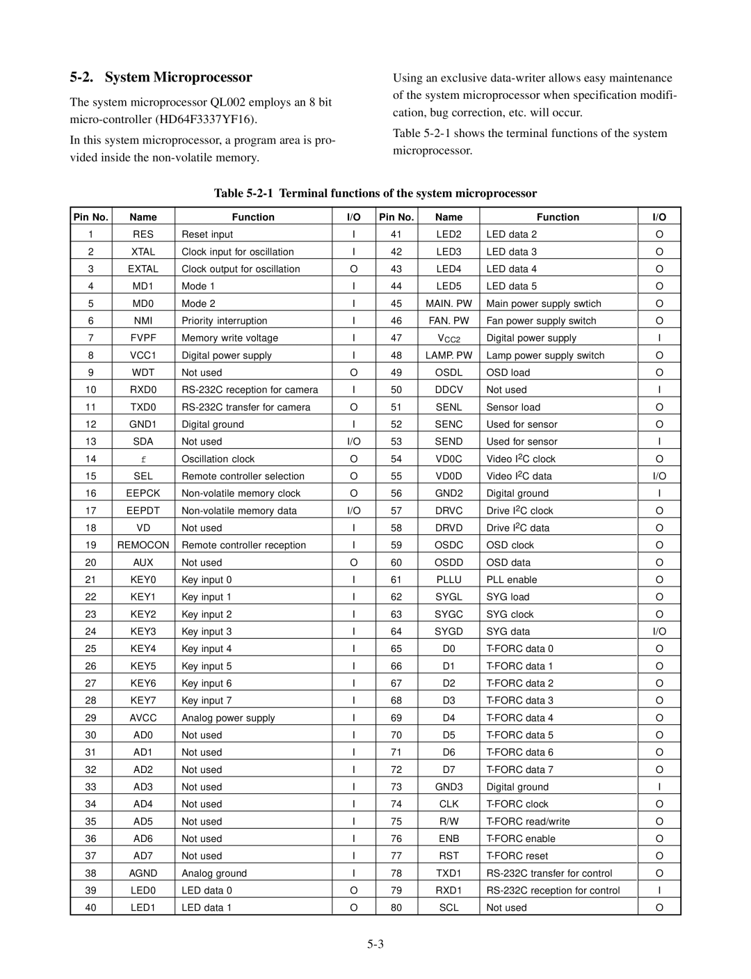
Table
Table 5-2-1 Terminal functions of the system microprocessor
Pin No. | Name | Function | I/O | Pin No. | Name | Function |
1 | RES | Reset input | I | 41 | LED2 | LED data 2 |
2 | XTAL | Clock input for oscillation | I | 42 | LED3 | LED data 3 |
3 | EXTAL | Clock output for oscillation | O | 43 | LED4 | LED data 4 |
4 | MD1 | Mode 1 | I | 44 | LED5 | LED data 5 |
5 | MD0 | Mode 2 | I | 45 | MAIN. PW | Main power supply swtich |
6 | NMI | Priority interruption | I | 46 | FAN. PW | Fan power supply switch |
7 | FVPF | Memory write voltage | I | 47 | VCC2 | Digital power supply |
8 | VCC1 | Digital power supply | I | 48 | LAMP. PW | Lamp power supply switch |
9 | WDT | Not used | O | 49 | OSDL | OSD load |
10 | RXD0 | I | 50 | DDCV | Not used | |
11 | TXD0 | O | 51 | SENL | Sensor load | |
12 | GND1 | Digital ground | I | 52 | SENC | Used for sensor |
13 | SDA | Not used | I/O | 53 | SEND | Used for sensor |
14 | f | Oscillation clock | O | 54 | VD0C | Video I2C clock |
15 | SEL | Remote controller selection | O | 55 | VD0D | Video I2C data |
16 | EEPCK | O | 56 | GND2 | Digital ground | |
17 | EEPDT | I/O | 57 | DRVC | Drive I2C clock | |
18 | VD | Not used | I | 58 | DRVD | Drive I2C data |
19 | REMOCON | Remote controller reception | I | 59 | OSDC | OSD clock |
20 | AUX | Not used | O | 60 | OSDD | OSD data |
21 | KEY0 | Key input 0 | I | 61 | PLLU | PLL enable |
22 | KEY1 | Key input 1 | I | 62 | SYGL | SYG load |
23 | KEY2 | Key input 2 | I | 63 | SYGC | SYG clock |
24 | KEY3 | Key input 3 | I | 64 | SYGD | SYG data |
25 | KEY4 | Key input 4 | I | 65 | D0 | |
26 | KEY5 | Key input 5 | I | 66 | D1 | |
27 | KEY6 | Key input 6 | I | 67 | D2 | |
28 | KEY7 | Key input 7 | I | 68 | D3 | |
29 | AVCC | Analog power supply | I | 69 | D4 | |
30 | AD0 | Not used | I | 70 | D5 | |
31 | AD1 | Not used | I | 71 | D6 | |
32 | AD2 | Not used | I | 72 | D7 | |
33 | AD3 | Not used | I | 73 | GND3 | Digital ground |
34 | AD4 | Not used | I | 74 | CLK | |
35 | AD5 | Not used | I | 75 | R/W | |
36 | AD6 | Not used | I | 76 | ENB | |
37 | AD7 | Not used | I | 77 | RST | |
38 | AGND | Analog ground | I | 78 | TXD1 | |
39 | LED0 | LED data 0 | O | 79 | RXD1 | |
40 | LED1 | LED data 1 | O | 80 | SCL | Not used |
|
|
|
|
|
|
|
I/O
O
O
O
O
O
O
I
O
O
I
O
O
I
O
I/O
I
O
O
O
O
O
O
O
I/O
O
O
O
O
O
O
O
O
I
O
O
O
O
O
I
O
