5-8. Status Display Process
In the status display process,
5-9. On-screen Display Process
In the
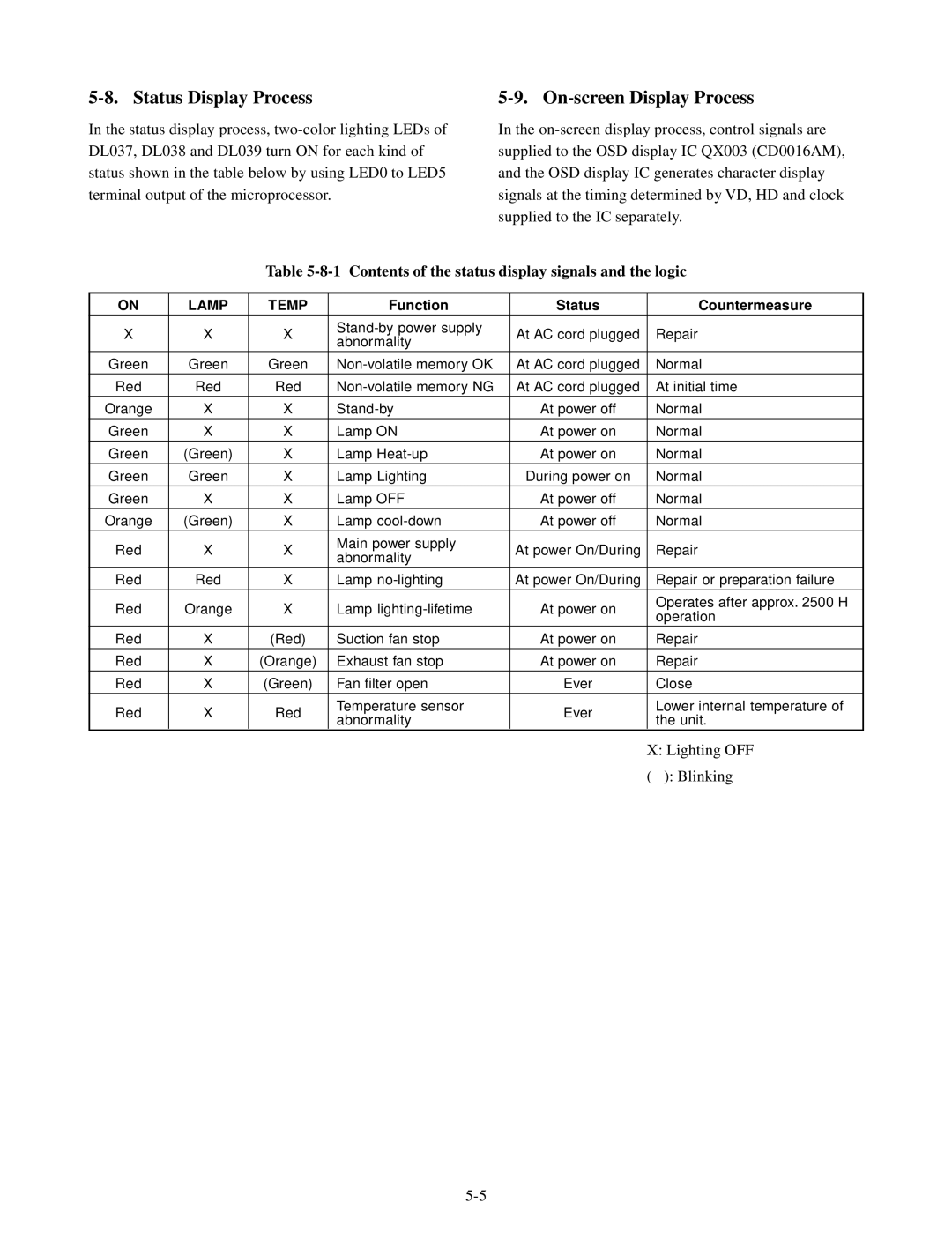
Table 5-8-1 Contents of the status display signals and the logic
ON | LAMP | TEMP | Function | Status | Countermeasure | |
X | X | X | At AC cord plugged | Repair | ||
abnormality | ||||||
|
|
|
|
| ||
Green | Green | Green | At AC cord plugged | Normal | ||
Red | Red | Red | At AC cord plugged | At initial time | ||
Orange | X | X | At power off | Normal | ||
|
|
|
|
|
| |
Green | X | X | Lamp ON | At power on | Normal | |
Green | (Green) | X | Lamp | At power on | Normal | |
Green | Green | X | Lamp Lighting | During power on | Normal | |
Green | X | X | Lamp OFF | At power off | Normal | |
Orange | (Green) | X | Lamp | At power off | Normal | |
Red | X | X | Main power supply | At power On/During | Repair | |
abnormality | ||||||
|
|
|
|
| ||
Red | Red | X | Lamp | At power On/During | Repair or preparation failure | |
|
|
|
|
|
| |
Red | Orange | X | Lamp | At power on | Operates after approx. 2500 H | |
operation | ||||||
|
|
|
|
| ||
Red | X | (Red) | Suction fan stop | At power on | Repair | |
Red | X | (Orange) | Exhaust fan stop | At power on | Repair | |
Red | X | (Green) | Fan filter open | Ever | Close | |
Red | X | Red | Temperature sensor | Ever | Lower internal temperature of | |
abnormality | the unit. | |||||
|
|
|
|
X: Lighting OFF
( ): Blinking