Commander Installation Guide
2.4.3500-01 SERIES TDM CONTROLLER CARD The current version of the TDM card is:
• 500-01-10 which replaces the 500-01-00.
The main TDM controller is fitted in the left side of the frame, immediately to the right of the 500-08 / 500-02 combination. The standby controller is only applicable in fault tolerant systems when the appropriate modules have been purchased. Do not fit the standby controllers at this stage.
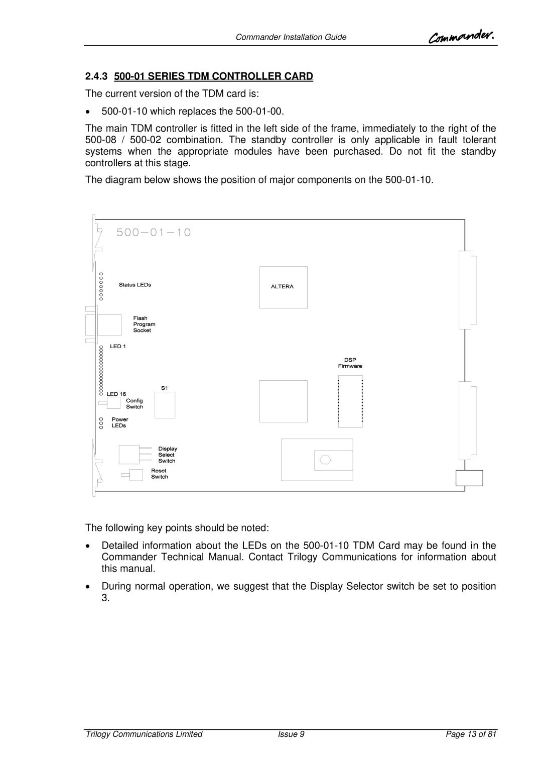
The diagram below shows the position of major components on the 500-01-10.
The following key points should be noted:
•Detailed information about the LEDs on the 500-01-10 TDM Card may be found in the Commander Technical Manual. Contact Trilogy Communications for information about this manual.
•During normal operation, we suggest that the Display Selector switch be set to position 3.
Trilogy Communications Limited | Issue 9 | Page 13 of 81 |

