Commander Installation Guide
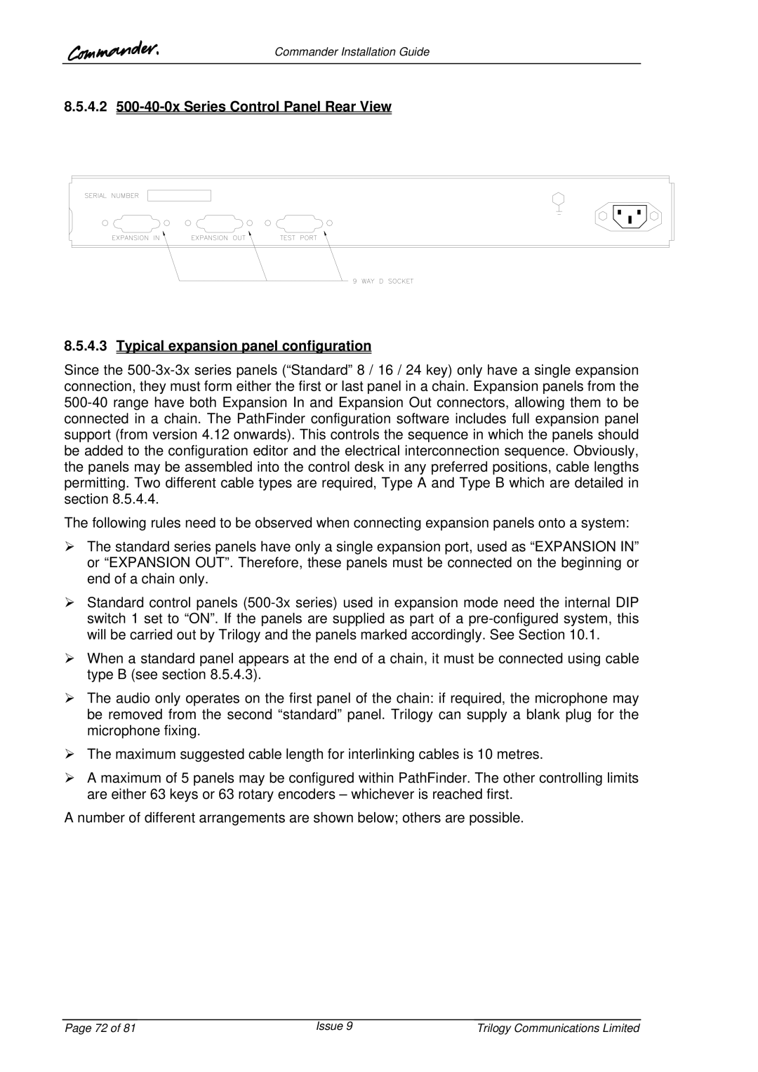
8.5.4.2
8.5.4.3Typical expansion panel configuration
Since the
The following rules need to be observed when connecting expansion panels onto a system:
¾The standard series panels have only a single expansion port, used as “EXPANSION IN” or “EXPANSION OUT”. Therefore, these panels must be connected on the beginning or end of a chain only.
¾Standard control panels
¾When a standard panel appears at the end of a chain, it must be connected using cable type B (see section 8.5.4.3).
¾The audio only operates on the first panel of the chain: if required, the microphone may be removed from the second “standard” panel. Trilogy can supply a blank plug for the microphone fixing.
¾The maximum suggested cable length for interlinking cables is 10 metres.
¾A maximum of 5 panels may be configured within PathFinder. The other controlling limits are either 63 keys or 63 rotary encoders – whichever is reached first.
A number of different arrangements are shown below; others are possible.
Page 72 of 81 | Issue 9 | Trilogy Communications Limited |