Commander Installation Guide
Keypad D9 Fixed Socket
Pin | Function | Notes |
1 | Column 1 | Switch 1,4,7, * |
2 | Column 3 | Switch 3,6,9,# |
3 | Row 2 | Switch 4,5,6 |
4 | Row 4 | Switch *,0,# |
5 | GND | For switch LEDs |
6 | Column 2 | Switch 2,5,8,0 |
7 | Row 1 | Switch 1,2,3 |
8 | Row 3 | Switch 7,8,9 |
9 | +12V out | Switch |
View of Keypad (as seen on front panel)
1 | 2 | 3 |
4 | 5 | 6 |
7 | 8 | 9 |
| 0 | # |
|
|
|
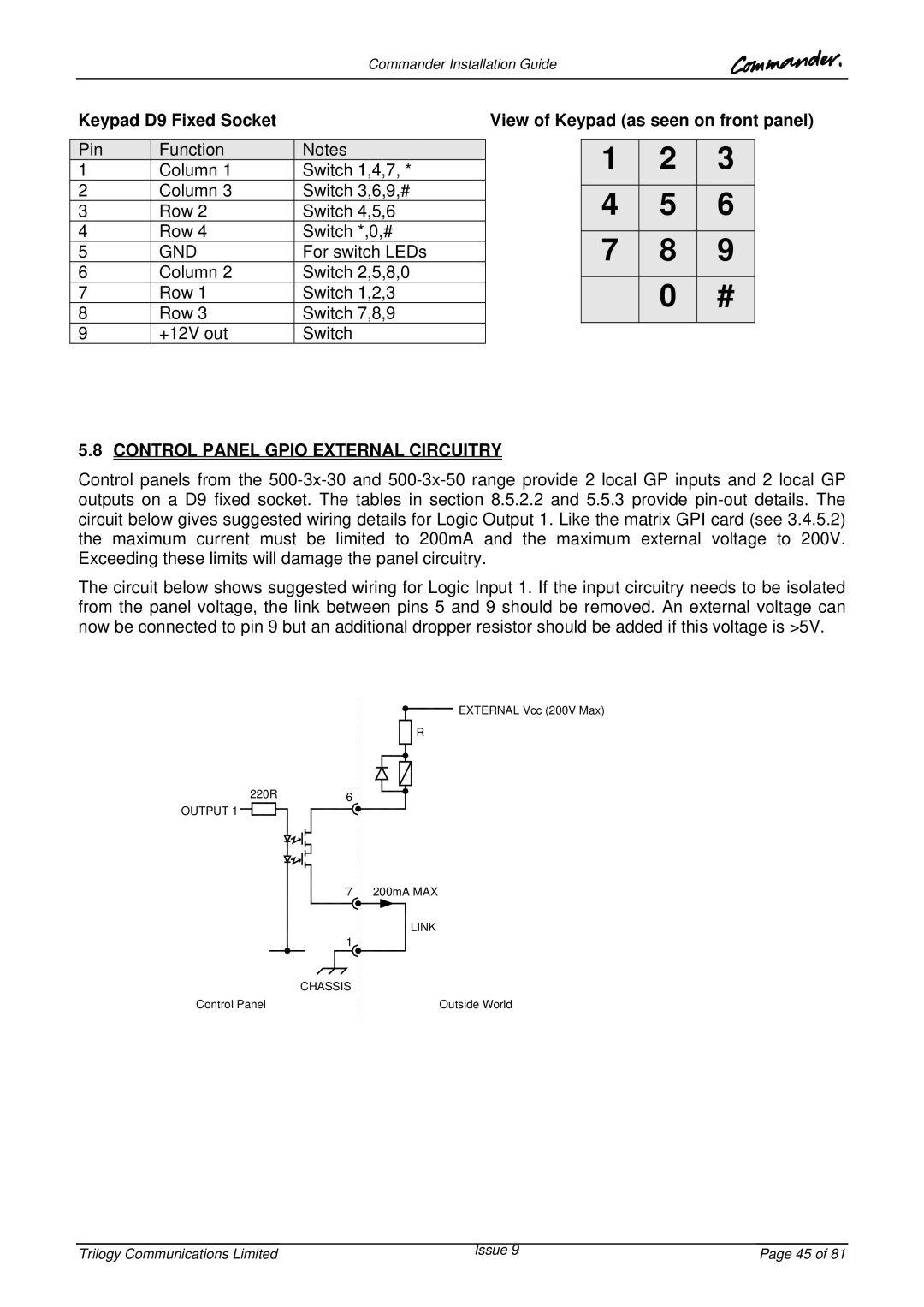
5.8CONTROL PANEL GPIO EXTERNAL CIRCUITRY
Control panels from the
The circuit below shows suggested wiring for Logic Input 1. If the input circuitry needs to be isolated from the panel voltage, the link between pins 5 and 9 should be removed. An external voltage can now be connected to pin 9 but an additional dropper resistor should be added if this voltage is >5V.
EXTERNAL Vcc (200V Max)
![]() R
R
220R | 6 |
OUTPUT 1
7 200mA MAX LINK
1![]()
CHASSIS
Control Panel
Outside World
Trilogy Communications Limited | Issue 9 | Page 45 of 81 |