Input Delay Buffers

IOBs of the FPGA device. The use of these delay buffers is selected through the implementation specific constraints file

R

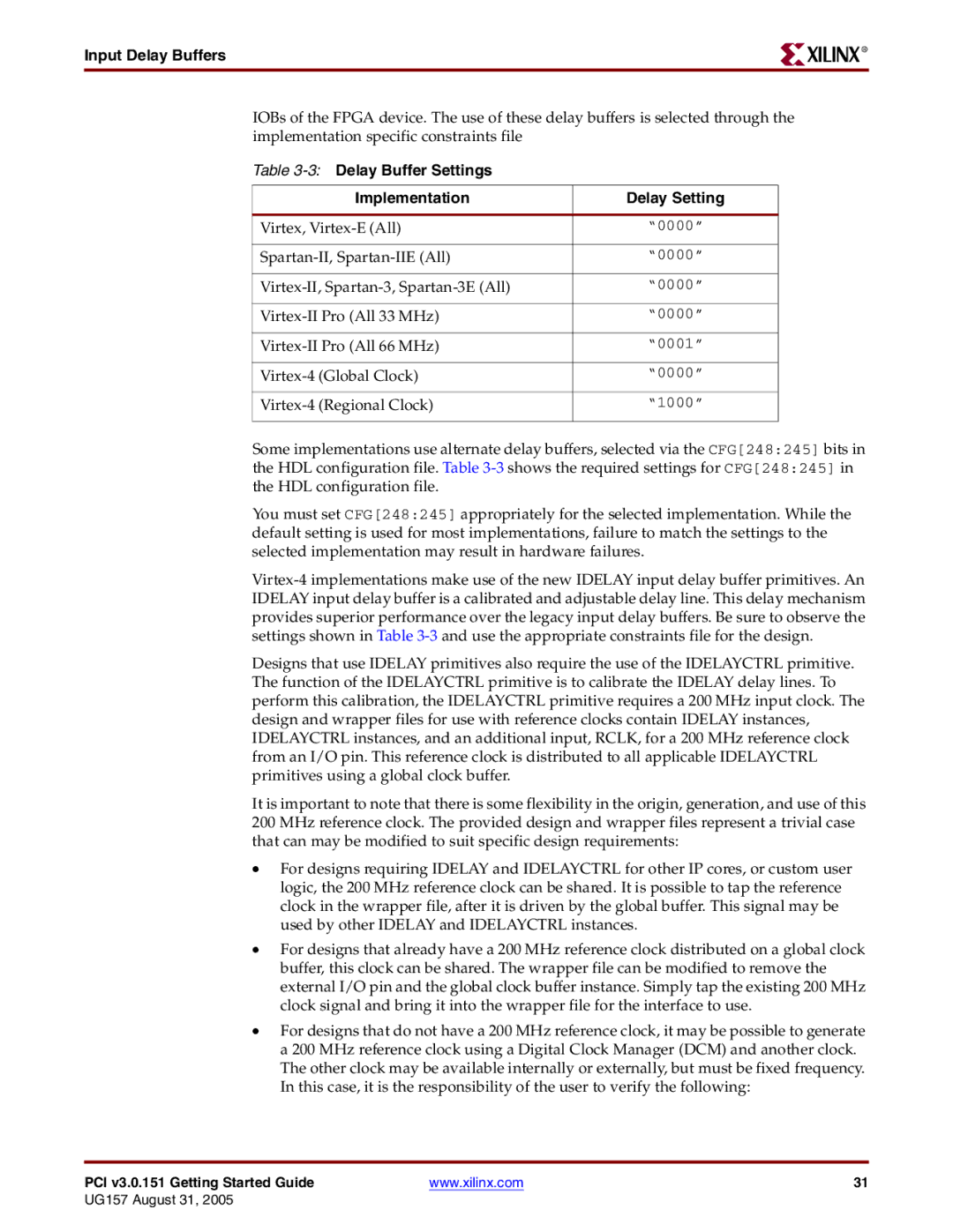
Table 3-3:Delay Buffer Settings


Implementation

Delay Setting


Virtex, Virtex-E (All)

“0000”


Spartan-II, Spartan-IIE (All)

“0000”


Virtex-II, Spartan-3, Spartan-3E (All)

“0000”


Virtex-II Pro (All 33 MHz)

“0000”


Virtex-II Pro (All 66 MHz)

“0001”


Virtex-4

(Global Clock)

“0000”


Virtex-4

(Regional Clock)

“1000”


Some implementations use alternate delay buffers, selected via the CFG[248:245] bits in the HDL configuration file. Table 3-3shows the required settings for CFG[248:245] in the HDL configuration file.

You must set CFG[248:245] appropriately for the selected implementation. While the default setting is used for most implementations, failure to match the settings to the selected implementation may result in hardware failures.

Virtex-4 implementations make use of the new IDELAY input delay buffer primitives. An IDELAY input delay buffer is a calibrated and adjustable delay line. This delay mechanism provides superior performance over the legacy input delay buffers. Be sure to observe the settings shown in Table 3-3and use the appropriate constraints file for the design.

Designs that use IDELAY primitives also require the use of the IDELAYCTRL primitive. The function of the IDELAYCTRL primitive is to calibrate the IDELAY delay lines. To perform this calibration, the IDELAYCTRL primitive requires a 200 MHz input clock. The design and wrapper files for use with reference clocks contain IDELAY instances, IDELAYCTRL instances, and an additional input, RCLK, for a 200 MHz reference clock from an I/O pin. This reference clock is distributed to all applicable IDELAYCTRL primitives using a global clock buffer.

It is important to note that there is some flexibility in the origin, generation, and use of this 200 MHz reference clock. The provided design and wrapper files represent a trivial case that can may be modified to suit specific design requirements:

For designs requiring IDELAY and IDELAYCTRL for other IP cores, or custom user logic, the 200 MHz reference clock can be shared. It is possible to tap the reference clock in the wrapper file, after it is driven by the global buffer. This signal may be used by other IDELAY and IDELAYCTRL instances.

For designs that already have a 200 MHz reference clock distributed on a global clock buffer, this clock can be shared. The wrapper file can be modified to remove the external I/O pin and the global clock buffer instance. Simply tap the existing 200 MHz clock signal and bring it into the wrapper file for the interface to use.

For designs that do not have a 200 MHz reference clock, it may be possible to generate a 200 MHz reference clock using a Digital Clock Manager (DCM) and another clock. The other clock may be available internally or externally, but must be fixed frequency. In this case, it is the responsibility of the user to verify the following:

PCI v3.0.151 Getting Started Guide

www.xilinx.com

31

UG157 August 31, 2005

Page 31
Image 31
Xilinx PCI v3.0 manual Input Delay Buffers, 3Delay Buffer Settings Implementation Delay Setting

PCI v3.0 specifications

Xilinx PCI Express (PCIe) v3.0 technology represents a significant leap in performance and efficiency for high-speed data transfer applications. As a critical interface standard for connecting peripheral devices to a host system, PCIe v3.0 introduces numerous enhancements that ensure faster data rates, increased bandwidth, and lower latency, meeting the rigorous demands of modern computing environments.

One of the standout features of PCIe v3.0 is its increased data transfer rate, which doubles the bandwidth compared to its predecessor, PCIe v2.0. This version supports a maximum theoretical bandwidth of 8 GT/s (gigatransfers per second) per lane, leading to an aggregate bandwidth of up to 32 GB/s with four lanes operating simultaneously, which is crucial for applications in data-intensive fields such as telecommunications, data centers, and high-performance computing.

Xilinx’s PCIe v3.0 solutions incorporate advanced error-handling mechanisms and improved power management. The technology employs a robust 128/130b encoding scheme that minimizes overhead while ensuring data integrity. Additionally, PCIe v3.0 supports native high-speed signaling, which not only reduces power consumption but also enhances signal quality, leading to greater reliability in data transmission.

The flexibility of Xilinx’s PCIe v3.0 implementation makes it ideal for various applications, including artificial intelligence, machine learning, and video processing, where rapid data throughput is paramount. Moreover, Xilinx provides extensive support through its Vivado Design Suite, enabling developers to easily integrate PCIe functionality into their designs while optimizing performance for specific applications through customizable settings.

Another key characteristic is the backward compatibility with earlier PCIe versions. This ensures that existing hardware can leverage new capabilities without necessitating a complete overhaul of the infrastructure, enhancing investment protection for users. The inclusion of additional features such as enhanced message signaling and the ability to support up to 64 thousand in-flight transactions further boosts the efficiency of data handling in a multi-threaded environment.

In summary, Xilinx PCI Express v3.0 technology is a powerful solution that combines high bandwidth, reduced latency, and enhanced reliability, making it an essential component for advanced computing architectures. Its robust features, coupled with Xilinx’s design tools and support, provide developers with the resources needed to push the boundaries of data transfer capabilities in a growing range of applications.