E-IDE (ATAPI) Connection Set Up
Installing the CRW2200E
6As an supplemental drive:
Remove the front cover of a vacant
As a replacement drive:
Remove the device such as
7Slide the drive backwards into the slot, then tighten the four fastening screws on the sides of the unit to hold the drive in place.
(→P. 26 step 11)
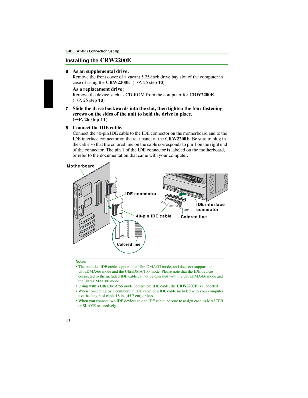
8Connect the IDE cable.
Connect the
Motherboard
IDE connector
IDE interface connector
Colored line |
![]() 1
1
Colored line
Notes
•The included IDE cable supports the UltraDMA/33 mode, and does not support the UltraDMA/66 mode and the UltraDMA/100 mode. Please note that the IDE devices connected to the included IDE cable cannot be operated with the UltraDMA/66 mode and the UltraDMA/100 mode.
•Using with a UltraDMA/66 mode compatible IDE cable, the CRW2200E is supported.
•When connecting by a commercial IDE cable or a IDE cable included with your computer, use the length of cable 18 in. (45.7 cm) or less.
•When you connect two IDE devices to one IDE cable, be sure to assign each as MASTER or SLAVE respectively.
43