Page
Page
Absolute Reset
Before using the robot Be sure to read the following notes
Setting the standard coordinates
Page
Introduction
Robot parameter has been changed. See in chapter
Clean Room Models YK120XC, YK150XC
Suction couplers have been added. See in chapter
Contents
Adjustment
Increasing the robot operating speed
Memo
Chapter
Memo
Safety Information
Essential Caution Items
Observe the following cautions during automatic operation
Follow the instructions on warning labels and in this manual
Use caution when releasing the Z-axis vertical axis brake
Provide safety measures for end effector gripper, etc
12Cautions for removing Z-axis brake or Z-axis motor
13Use the following caution during inspection of controller
17Do not remove, alter or stain the warning labels
Damage or Trouble Possible Danger
19Always connect the robot to the specified controller
22Be sure to make correct parameter settings
18Protective bonding
23Do not use the robot for tasks requiring motor thrust
27Caution when turning off the robot controller
24Do not apply excessive force to each section
28Take the following precautions when transporting the robot
Special Training for Industrial Robot Opera- tion
Robot Safety Functions
Safety Measures for the System
Trial Operation
Work Within the Safeguard Enclosure
Automatic Operation
Adjustment and Inspection
Repair and Modification
Warranty
Warranty description
Using the Robot Safely
CE Marking
Functions
Memo
Robot Manipulator
Manipulator movement
YK120X, YK150X
YK120XC, YK150XC
YK180X, YK220X
Robot Controller
Robot controller for YK120X series YK120X, YK150X
Robot initialization number list
Robot initialization number
Parameters for Clean Room Models YK120XC, YK150XC
To purchasers of this robot
Memo
Installation
Memo
Robot Installation Conditions
Installation environments
Installation
Installation base
Maximum reaction force applied during operation
Installation
Installation
Unpacking
Product configurations
Checking the product
Moving the robot
Installing the robot
Symbol 417-IEC-5019
Protective Bonding
Ground terminal
Robot Cable Connection
Robot cable connections
User Wiring and User Tubing
Lock mechanism Cable to be
Arm side and base side connector supplied
Connecting a suction hose YK120XC, YK150XC
Attaching The End Effector
Installation
Acceleration coefficient vs. moment of inertia YK120X
=0.4kg
Acceleration coefficient vs. moment of inertia YK150X
00005 100 Kgm 0010
Installation
Equation for moment of inertia calculation
Ρπ D 2 h Kgm
WD2
Example of moment of inertia calculation
When the workpiece form
Attaching the end effector
FXYmax FZmax FRmax MRmax Mmax
24 Maximum load applied to end effector attachment
YK120X, YK150X Axis
Gripping force of end effector
Maximum acceleration during robot operation
Axis R-axis has no mechanical stoppers
Memo
Adjustment
Memo
Safety Precautions
Overview
Adjusting the origin
View of R-axis from below
Stroke end method X-axis, Y-axis
Default origin position YK120X, YK150X, YK120XC, YK150XC
Stroke end method Z-axis
2 YK180X series YK180X, YK220X Sensor method R-axis
Default origin position
Sensor method X-axis, Y-axis
Stroke end method Z-axis
Machine reference
Machine reference
Machine reference value = B/A ⋅ 100%
Machine reference display on MPB screen
Absolute reset procedures Sensor method R-axis
Adjustment
Stroke end method X and Y axes of YK120X, YK150X
Adjustment
Stroke end method Z-axis
Sensor method X and Y axes of YK180X, YK220X
Adjustment
Adjusting the machine reference
Adjustment
Adjustment of R-axis machine reference View from below
Adjusting the R-axis machine reference YK120XC, YK150XC
Adjustment of R-axis machine reference
Adjusting the X-axis machine reference
Adjustment of X-axis machine reference
Adjusting the Y-axis machine reference
10 Adjustment of Y-axis machine reference
Adjusting the Z-axis machine reference
Adjustment
Section
Adjustment
Axis Sensor Axis dog Bolt
Adjusting the X-axis machine reference
13 Adjustment of X-axis machine reference
Adjusting the Y-axis machine reference
14 Adjustment of Y-axis machine reference
Adjusting the Z-axis machine reference
Adjustment
Adjustment
Setting the Soft Limits
Setting the X-axis and Y-axis soft limits
Adjustment
Setting the Z-axis soft limits
Setting the Standard Coordinates
Affixing Stickers for Movement Directions and Axis Names
17 Positions for affixing the stickers
Removing the Robot Covers
YK120XC, YK150XC
Base rear cover
Memo
Periodic Inspecition
Memo
Periodic Inspection
Precautions
Inspection to be performed with the controller turned off
Daily Inspection
Inspection to be performed with the controller turned on
Adjustment and parts replacement
Six-Month Inspection
Bolt tightening torque
After turning on the controller, check the following points
Replacing the Harmonic Drive Grease
Replacement period
Harmonic drive speed reduction ratio
Periodic Inspection
Recommended grease
Increasing the robot operating speed
Memo
Increasing the robot operating speed
Increasing speed by arch motion
Arch motion Making the arch position value larger
Increasing the robot operating speed
Move P, P2
Increasing the speed by the OUT effective position parameter
Memo
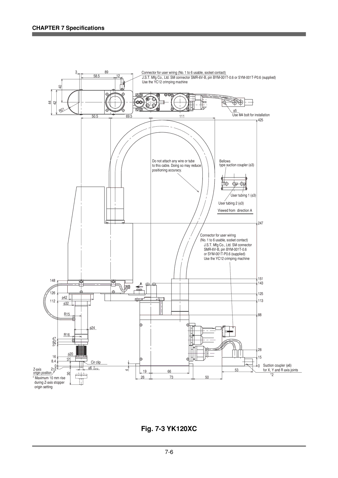
Specifications
Memo
Basic specification
Manipulator
External view and dimensions
YK120X
139 113
YK150X
139
YK120XC
R50
YK150XC
139
YK180X
120
YK220X
140
Robot inner wiring diagram
Rorg Rorg ZBK ZBK
Wiring table
Robot cable wiring table
Machine harness wiring table
Origin sensor wiring table
Connector
Memo
Scara Robots