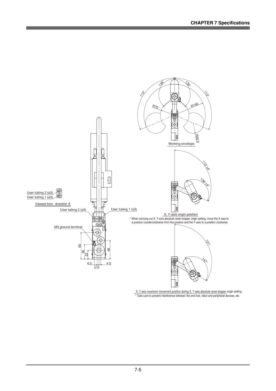
YK120X, YK180X specifications
The Yamaha YK180X and YK120X are two of the latest offerings from Yamaha in the sphere of high-performance synthesizers, designed to cater to both novice and professional musicians. These models are part of Yamaha's commitment to innovation, combining advanced technologies with user-friendly interfaces to create instruments that inspire creativity.The YK180X stands out with its 88 weighted keys that emulate the feel of an acoustic piano. This feature is particularly beneficial for pianists who seek a realistic playing experience. In contrast, the YK120X offers 61 semi-weighted keys, making it more portable while still providing a satisfying touch that balances playability and responsiveness. Both models incorporate Yamaha's renowned Graded Hammer Standard action, ensuring that the playing experience aligns with traditional piano dynamics.
One of the key technological advancements in both models is the integrated Pure CF Sound Engine. This technology captures the nuances of Yamaha's acclaimed concert grand pianos, delivering rich and authentic sound across a wide range of musical styles. Additionally, the synthesis engines in these synths allow for an expansive palette of sounds, from lush strings and bold brass to rich synthetic tones, enabling musicians to explore various genres effortlessly.
Another impressive feature of the YK180X and YK120X is the extensive library of built-in voices and styles. The YK180X boasts over 600 voices and 200 styles, while the YK120X comes with a diverse selection of over 400 voices and 150 styles, providing users with an array of options to enhance their performance. Both models also include a user-friendly interface with intuitive navigation, allowing for quick access to features and customization.
Connectivity is a critical aspect, and both synthesizers include USB to Host ports for easy integration with computers and mobile devices. With MIDI in and out options, musicians can connect to other musical gear, making these models versatile companions for stage performances and studio recordings alike.
In terms of additional features, the YK180X and YK120X come equipped with a built-in metronome and transpose functions, essential tools for practicing and performing. Moreover, the onboard recording capabilities allow musicians to capture their ideas and compositions quickly and efficiently.
Overall, the Yamaha YK180X and YK120X are powerful and versatile synthesizers that cater to a wide range of musical needs, from home practice to professional settings. With their superior sound quality, realistic playability, and innovative features, they represent an excellent choice for musicians looking to elevate their musical journey.

