OWNERS MANUAL
Page
2. Setting the standard coordinates
Before using the robot Be sure to read the following notes
1. Absolute Reset
Error messages issued when robot & controller are connected RCX142
2 Caution when turning off the robot controller
3 Connection to the controller
Introduction
IM Company
Clean Room Models YK120XC, YK150XC
1. Robot parameter has been changed. See section 4 in chapter
2. Suction couplers have been added. See section 6 in chapter
CHAPTER 2 Functions
CHAPTER 1 Using the Robot Safely
Installation
CHAPTER
CHAPTER 4 Adjustment
Increasing the robot operating speed
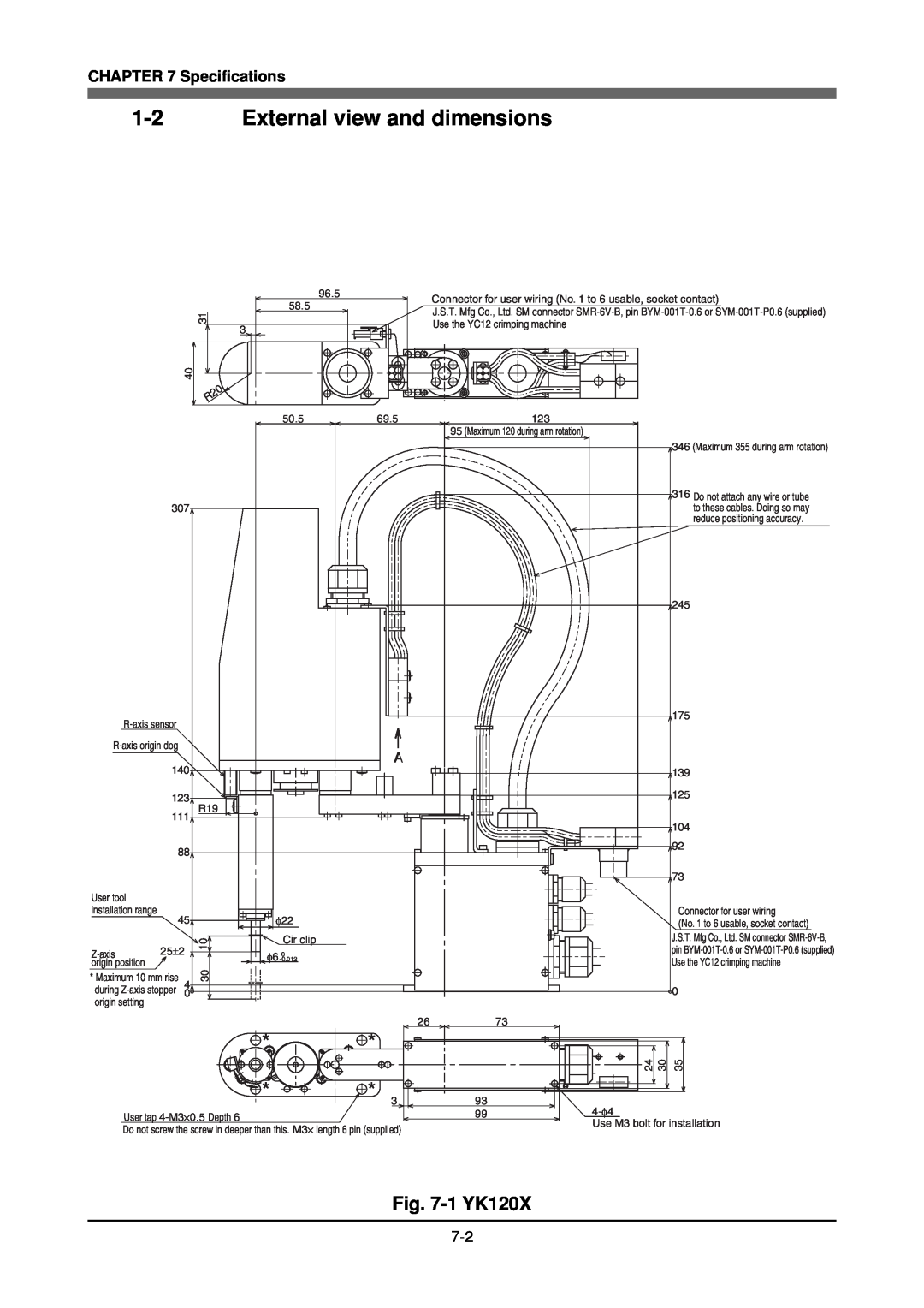
Specifications
Periodic Inspecition
CHAPTER
MEMO
Using the Robot Safely
CHAPTER
MEMO
1 Safety Information
DANGER
Fig. 1-1 Warning label
2 Essential Caution Items
1 Observe the following cautions during automatic operation
Fig. 1-2 Warning label
3 Follow the instructions on warning labels and in this manual
Fig. 1-3 Warning label
Read owners manual and all warning labels before operation
6 Use caution when releasing the Z-axis vertical axis brake
7 Provide safety measures for end effector gripper, etc
12Cautions for removing Z-axis brake or Z-axis motor
13Use the following caution during inspection of controller
15Use caution not to touch the controller rear panel cooling fan
17Do not remove, alter or stain the warning labels
19Always connect the robot to the specified controller
22Be sure to make correct parameter settings
18Protective bonding
21Do not use the robot in locations subject to strong vibrations
27Caution when turning off the robot controller
24Do not apply excessive force to each section
28Take the following precautions when transporting the robot
3 Special Training for Industrial Robot Opera- tion
2 Overheat detection
4 Robot Safety Functions
1 Overload detection
3 Soft limits
5 Safety Measures for the System
6 Trial Operation
7 Work Within the Safeguard Enclosure
9 Adjustment and Inspection
8 Automatic Operation
10 Repair and Modification
11 Warranty
CHAPTER 1 Using the Robot Safely
12 CE Marking
CHAPTER 1 Using the Robot Safely
Functions
CHAPTER
MEMO
1 Robot Manipulator
Fig. 2-1 Manipulator movement
CHAPTER 2 Functions
Fig. 2-2 YK120X, YK150X
Connector for user wiring No.1 to
User tubing 2 φ3
Ball screw Linear busing shaft
Fig. 2-3 YK120XC, YK150XC
Connector for user wiring No.1 to
CHAPTER 2 Functions
Fig. 2-4 YK180X, YK220X
CHAPTER 2 Functions
Viewed from direction A
2 Robot Controller
Fig. 2-5 Robot controller for YK120X series YK120X, YK150X
RCX142
3 Robot initialization number list
To purchasers of this robot
4 Parameters for Clean Room Models YK120XC, YK150XC
Precautions during use
Parameter changes
MEMO
Installation
CHAPTER
MEMO
1 Robot Installation Conditions
Installation environments
CHAPTER 3 Installation
F Xmax
Installation base
The maximum reaction force
M Xmax
Do not place the robot on a moving installation base. Excessive loads will be applied to the robot arm by movement of the installation base, resulting in dam- age to the robot
2 Installation
2-1 Unpacking
Fig. 3-2 Packed state
Standard
Fig. 3-3 Product configurations
2-2 Checking the product
Option
2-3 Moving the robot
Installing the robot
Fig. 3-5 Installing the robot
Symbol 417-IEC-5019
3 Protective Bonding
YK120X, YK150X
Fig. 3-6 Ground terminal
CHAPTER 3 Installation
YK180X, YK220X
4 Robot Cable Connection
Fig. 3-7 Robot cable connections
CHAPTER 3 Installation
User signal cable
5 User Wiring and User Tubing
User wiring
User tubing
3 Signal wiring connections in the machine harness
Connector pins 1 to 6 can be used
CHAPTER 3 Installation
Manufacture
SM Connector SMR-6V-B
Arm side and base side connector supplied
BYM-001T-0.6
Connecting a suction hose YK120XC, YK150XC
7 Attaching The End Effector
7-1 R-axis tolerable moment of inertia and acceleration coeffi- cient
Depending on the Z-axis position, vibration may occur when the X, Y or R-axis moves. If this happens, reduce the X, Y or R-axis acceleration to an appropri- ate level
W=0.1kg
7-1-1 Acceleration coefficient vs. moment of inertia YK120X
CHAPTER 3 Installation
W=0.2kg
CHAPTER 3 Installation
W=0.4kg
W=0.5kg
W=0.1kg
7-1-2 Acceleration coefficient vs. moment of inertia YK150X
CHAPTER 3 Installation
W=0.2kg
CHAPTER 3 Installation
W=0.4kg
W=0.5kg
CHAPTER 3 Installation
7-1-3
Acceleration coefficient vs. moment of inertia YK180X, YK220X
W=0.1 to 0.4kg
7-2 Equation for moment of inertia calculation
3 Moment of inertia for cylinder part
5 When the objects center line is offset from the rotation center
7-3 Example of moment of inertia calculation
3 Moment of inertia of workpiece
4 Total weight
2 Moment of inertia of the chuck
5 Total moment of inertia
FXYmax
7-4 Attaching the end effector
Fig. 3-23 Z-axis tip shape
FZmax
kgfcm
Fig. 3-24 Maximum load applied to end effector attachment
CHAPTER 3 Installation
Hole diameter
Make sure that excessive force is not applied to the joints
7-5 Gripping force of end effector
Table 3-3 Maximum acceleration during robot operation
Fig. 3-26 Maximum acceleration on end effector attachment
1 X and Y axes
MEMO
Adjustment
CHAPTER
MEMO
2 Safety Precautions
1 Overview
3 Adjusting the origin
3-1 Absolute reset method 3-1-1 YK120X series YK120X, YK150X
3-1-1-1 Sensor method R-axis
Fig. 4-1 View of R-axis from below
3-1-1-2 Stroke end method X-axis, Y-axis
Fig. 4-2 Default origin position YK120X, YK150X, YK120XC, YK150XC
CHAPTER 4 Adjustment
139 ±
3-1-1-3 Stroke end method Z-axis
CHAPTER 4 Adjustment
3-1-2 YK180X series YK180X, YK220X 3-1-2-1 Sensor method R-axis
side
Fig. 4-5 Default origin position
3-1-2-2 Sensor method X-axis, Y-axis
3-1-2-3 Stroke end method Z-axis
Never enter within the robot movement range during absolute reset
CHAPTER 4 Adjustment
Machine reference
3-2 Machine reference
Machine reference value = B/A ⋅ 100%
Machine reference display on MPB screen
3-3 Absolute reset procedures 3-3-1 Sensor method R-axis
7 Since the message Reset ABS encoder OK? is displayed, check that there are not any obstacles in the robot movement range, and press the F4 key YES
3-3-2 Stroke end method X and Y axes of YK120X, YK150X
8 After the absolute reset is completed, check that the X-axis and Y-axis ma- chine reference value displayed on the MPB is within the absolute reset tol- erance range 40 to
3-3-3 Stroke end method Z-axis
3-3-4 Sensor method X and Y axes of YK180X, YK220X
CHAPTER 4 Adjustment
3-4 Adjusting the machine reference
3-4-1-1 Adjusting the R-axis machine reference YK120X, YK150X
3-4-1 YK120X series YK120X, YK150X
Fig. 4-7 Adjustment of R-axis machine reference View from below
3-4-1-2 Adjusting the R-axis machine reference YK120XC, YK150XC
Fig. 4-8 Adjustment of R-axis machine reference
3-4-1-3 Adjusting the X-axis machine reference
Fig. 4-9 Adjustment of X-axis machine reference
X-axis arm X-axis fixed mechanical stopper B A Bolt
3-4-1-4 Adjusting the Y-axis machine reference
Fig. 4-10 Adjustment of Y-axis machine reference
Y-axis moveable mechanical stopper BA X-axis arm
Bolt On back side of arm
3-4-1-5 Adjusting the Z-axis machine reference
The point data must be reset after adjusting the machine reference
When machine reference5%
Section
CHAPTER 4 Adjustment
3-4-2-1 Adjusting the R-axis machine reference YK180X, YK220X
3-4-2 YK180X series YK180X, YK220X
12 Perform the absolute reset from outside the safeguard enclosure
3-4-2-2 Adjusting the X-axis machine reference
Fig. 4-13 Adjustment of X-axis machine reference
B A Bolt X-axis dog X-axis Sensor
3-4-2-3 Adjusting the Y-axis machine reference
Fig. 4-14 Adjustment of Y-axis machine reference
3-4-2-4 Adjusting the Z-axis machine reference
Prop up the Z-axis with a support stand before beginning the work
Z-axis upper-end mechanical stopper
CHAPTER 4 Adjustment
Lower end urethane damper Ball screw Bolt Z-axis motor Spline nut
Bolt Upper end urethane damper
4 Setting the Soft Limits
1 Setting the X-axis and Y-axis soft limits
7 Set the soft limits to within the figure for the X-axis andY-axis encoder pulses that you noted above in step 5. This software limit setting must be made from outside the safeguard enclosure
Make this setting from outside the safeguard enclosure
5 Setting the Standard Coordinates
6 Affixing Stickers for Movement Directions and Axis Names
A B X Y Z R
Fig. 4-17 Positions for affixing the stickers
CHAPTER 4 Adjustment
+ Y - + R
7 Removing the Robot Covers
YK120XC, YK150XC
CHAPTER 4 Adjustment
YK120X, YK150X
same on opposite side
Y-axis arm upper cover qM3⋅6 ⋅4 wM3⋅6 ⋅4 eM3⋅6 ⋅4
CHAPTER 4 Adjustment
YK180X, YK220X
Base front cover
MEMO
Periodic Inspecition
5-1 Replacement period
CHAPTER
MEMO
1 Overview
Periodic inspection includes Daily inspection 6-month inspection
2 Precautions
3 Daily Inspection
1 Inspection to be performed with the controller turned off
2 Inspection to be performed with the controller turned on
3 Adjustment and parts replacement
4 Six-Month Inspection
Take the following precautions when performing 6-month inspection
CHAPTER 5 Periodic Inspection
Procedure
1 Inspection to be performed with the controller turned off
1 Bolt tightening torque
2 Inspection to be performed with the controller turned on
3 Adjustment and parts replacement
Check for dust on the fan cover. Remove and clean if necessary
Check if the fan rotates normally
5-1 Replacement period
5 Replacing the Harmonic Drive Grease
Table 5-1 Harmonic drive speed reduction ratio
Page
Recommended grease
Use the following harmonic drive grease
SK-2 made by Harmonic Drive Systems Inc
Increasing the robot operating speed
CHAPTER
MEMO
q Gate motion
1 Increasing the robot operating speed
1 Increasing speed by arch motion
Axis parameters - Arch position
e Arch motion Making the arch position value larger
Robot parameters - Axis tip weight in Chapter 4 Programming manual
= 80 ....... Returns the tolerance to the default value
OUTPOS 2 = 10000 ... Y-axis OUT effective position pulses
4 Increasing the speed by the OUT effective position parameter
OUTPOS 1 = 10000 ... X-axis OUT effective position pulses
OUTPOS 3 = 10000 ... Z-axis OUT effective position pulses
MEMO
Specifications
CHAPTER
MEMO
CHAPTER 7 Specifications
Basic specification
1 Manipulator
69.5mm
1-2 External view and dimensions
Fig. 7-1 YK120X
CHAPTER 7 Specifications
139 ±
CHAPTER 7 Specifications
139 113
R120
Fig. 7-2 YK150X
CHAPTER 7 Specifications
User tool installation range
CHAPTER 7 Specifications
13 9 ±
Fig. 7-3 YK120XC
CHAPTER 7 Specifications
CHAPTER 7 Specifications
Fig. 7-4 YK150XC
CHAPTER 7 Specifications
CHAPTER 7 Specifications
139 113
Fig. 7-5 YK180X
CHAPTER 7 Specifications
7-10
CHAPTER 7 Specifications
R75.7
7-12
Fig. 7-6 YK220X
CHAPTER 7 Specifications
Viewed from direction C
CHAPTER 7 Specifications
R109
Y-axis motor
1-3 Robot inner wiring diagram
CHAPTER 7 Specifications
Z-axis brake
CHAPTER 7 Specifications
1-4 Wiring table
Robot cable wiring table
7-15
Machine harness wiring table
CHAPTER 7 Specifications
Yellow Green
Brake wiring table
Motor wiring table
Origin sensor wiring table
CHAPTER 7 Specifications
CHAPTER 7 Specifications
Connector
Blue
MEMO
OWNERS MANUAL
SCARA Robots