Tripp Lite SU20KX, SU80KX, SU40KX owner manual Default Display, Status Display

Page 34

110 – Display and Configuration (continued)

10-3 Default Display
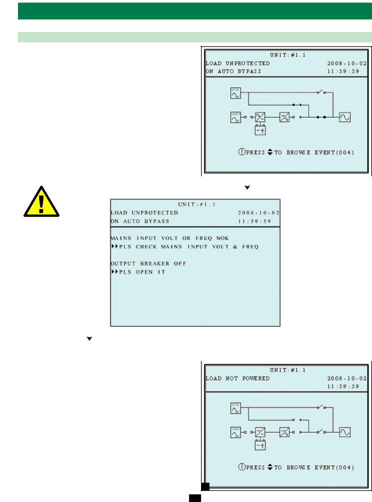
1 After the UPS system starts up and completes the self-test, the 2 LCD status screen will show the default display. The default

display includes a status message and diagram that shows the operational status of the UPS system.

3


4


5


1


6


When any event occurs, you will see the sign “!” flashes. You can press “ ” to see the details. For example:


7


8


9


10


Press “ ” again to go to the next message. If there is no further message, the screen will return to the default screen.


10-3-1 Status Display


11


The UPS system output is off and the connected equipment loads


1


are not powered. This condition may be due to automatic UPS


shutdown or manually switching off the output circuit breaker


switch.

12


Possible causes:


• The UPS automatically shuts down by itself.


Manually switch off the output circuit breaker.

13

14

1

34

Image 34
Contents Not suitable for mobile applications Table of Contents Advanced Features IntroductionLocation Warnings Important Safety InstructionsConnection Warnings Battery Warnings Wiring WarningsControl Panel Features Front and Rear Panel Features Output Circuit Breaker Switch Q4 Controls AC output powerFor more information about the Snmpwebcard accessory Preparation Cabinet InstallationUnpacking Rear, not from the sides PlacementShipping container. Warning The UPS system could tip if it Rear of the UPS systemInternal Battery Wiring Diagrams SU40KX shownInternal Battery Connection Internal Battery Connection Procedure Potential arcing of connectors. Blown fuses must be replaced Type and ratingInternal Battery Connection Wiring Wiring PreparationUPS System Terminal Block Diagram External Battery Cabinet Wiring DiagramsExternal Battery Cabinets Electrical and Cable DataExternal Battery Cabinet Wiring Failure to observe proper phase will damage the UPS system AC Input/Output Wiring Single UPSCreate a risk of personal injury and property damage AC Input/Output Wiring Parallel UPS Single Input Source Parallel UPS WarningsAuto Bypass Mode Single UPS Online Normal Mode Single UPSBattery Backup Mode Single UPS 10 8-4 Manual Bypass Mode Single UPSBattery Backup Mode Parallel UPS Online Mode Parallel UPSAuto Bypass Mode Parallel UPS Manual Bypass Mode Parallel UPS Hot Standby Mode Parallel UPSStandard Start-Up Procedure Single UPS Control Panel and Breaker DiagramsPreliminary Checklist Single UPS Start-Up, Shutdown and BypassBattery Start-Up Procedure Single UPS Manual Bypass Procedure Single UPS Shutdown Procedure Single UPSPreliminary Checklist Parallel UPS Start-Up Procedure Parallel UPS Shutdown Procedure Parallel UPS Manual Bypass Procedure Parallel UPS Switching from Manual Bypass to Normal Mode Parallel UPS Control Panel Diagram Display and ConfigurationDisplay Hierarchy Default Display Status DisplayStatus Display Battery power Main Menu UPS System Measure Menu UPS Setup Administrator Qualified service personnel UserBypass Setup Press ESC to return to the UPS Setup menu Output Setup Output Voltage Press ESC to return to the UPS Setup menu Battery Setup Redundancy10 3 Battery Strings Press ESC to return to the UPS Setup menu Battery Next Replace DateCharger Setup Parallel Group Parallel SetupParallel ID Battery Auto Test Control & Test SetupBuzzer Clear Battery Test Result Manual Battery TestForce Boost Charge Press ESC to return to the UPS Setup menu Local Setup Date Format LCD ContrastUser Password Administrator PasswordLanguage Firmware Version MaintenanceStatistics Use or to read the event log, then press to AdvanceCommunications Interfaces CommunicationsSnmpwebcard Slot Input Dry Contact Interface External Battery Cabinet Temperature Inputs Remote Emergency Power Off EPO Circuit DiagramAuxiliary Dry Contact Input Circuit Diagram External Battery Status InputOutput Dry Contact Interface Detail Default MessagesOptional Messages Parallel Configuration Port Output Dry Contact Circuit Diagram11-10 RS-232 Serial Port Circuit Diagram Hardware Pin AssignmentSpecifications UPS System Technical Specifications Optional MessagesService Storage and ServiceWarranty Storage