Ampro Corporation 700 manual Watchdog Timer, Serial Console Setup

Page 58

Chapter 3

Hardware

Serial Console Setup

The serial console feature is implemented by connecting a standard null modem cable or a modified serial cable (or “Hot Cable”) between one of the serial ports, such as Serial 1 (J5A), and the serial terminal or a PC with communications software. The BIOS Setup Utility controls the serial console settings on the ReadyBoard 700. Refer to Chapter 4, BIOS Setup for the settings of the serial console option, the serial terminal, or PC with communications software and the connection procedure.

Hot (Serial) Cable

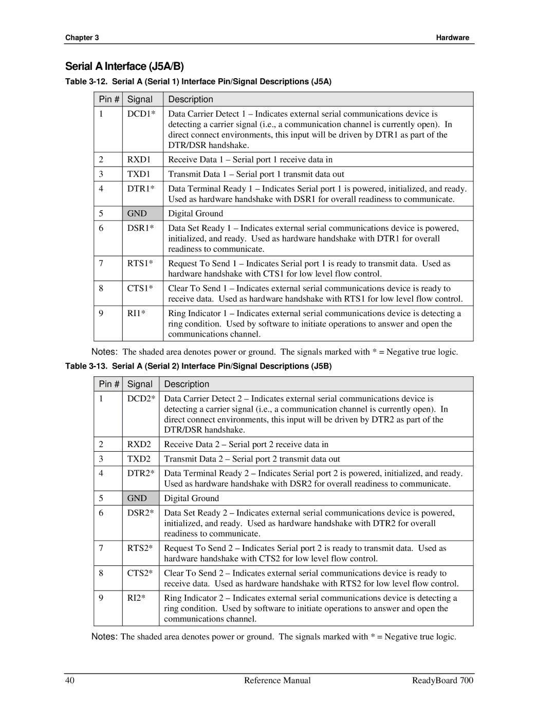
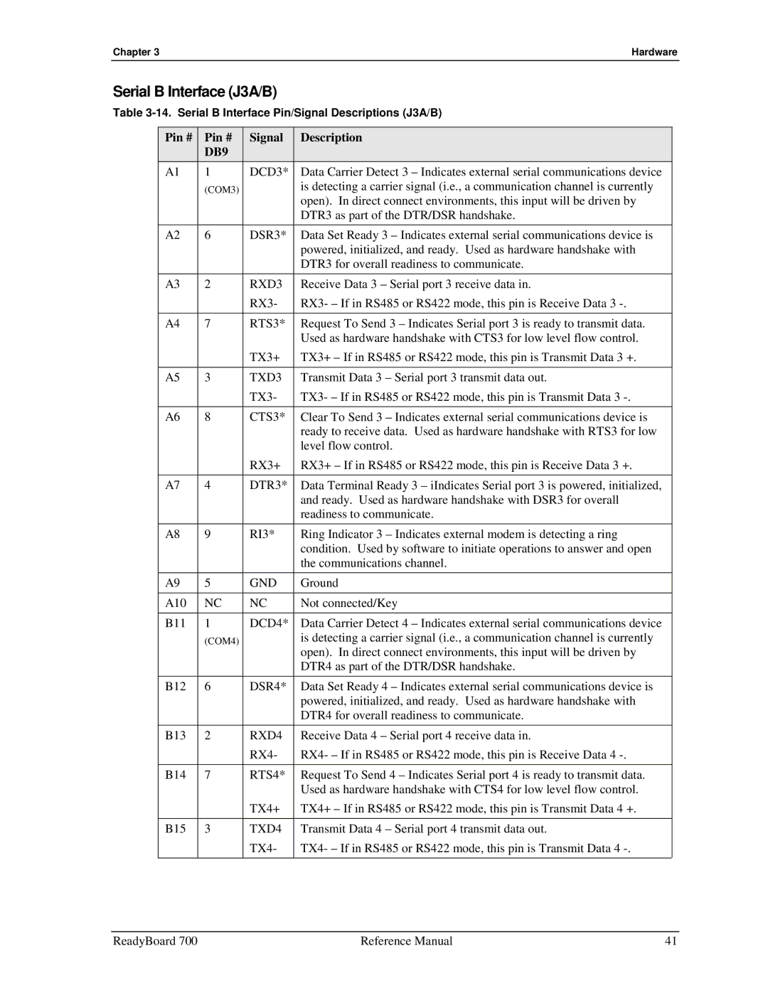
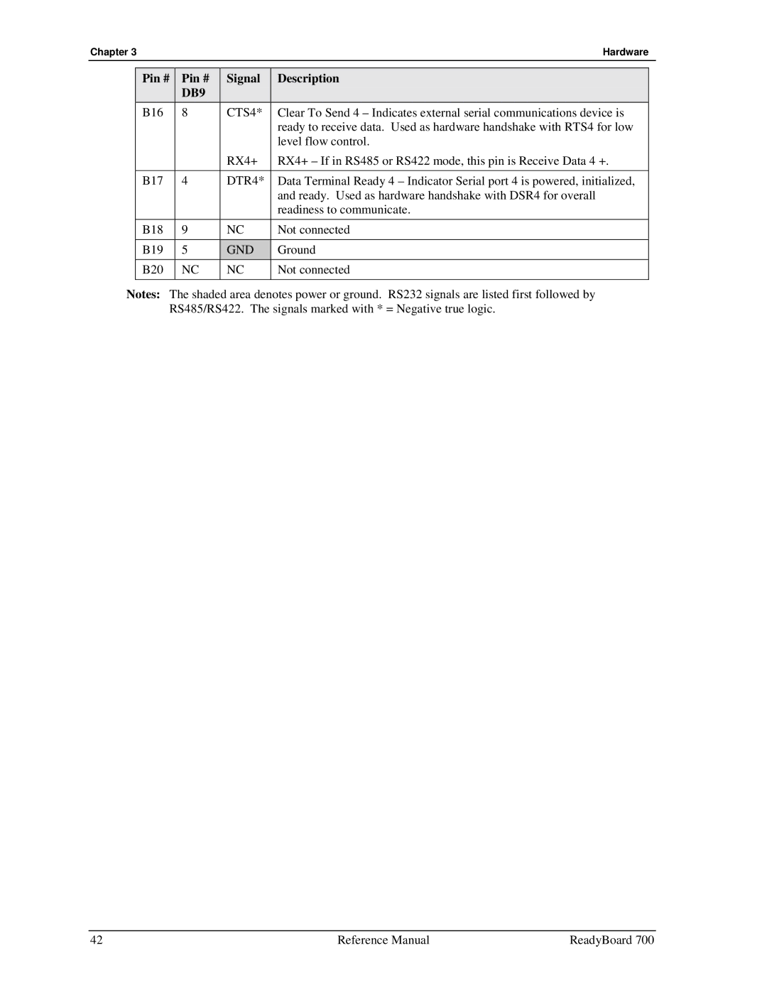
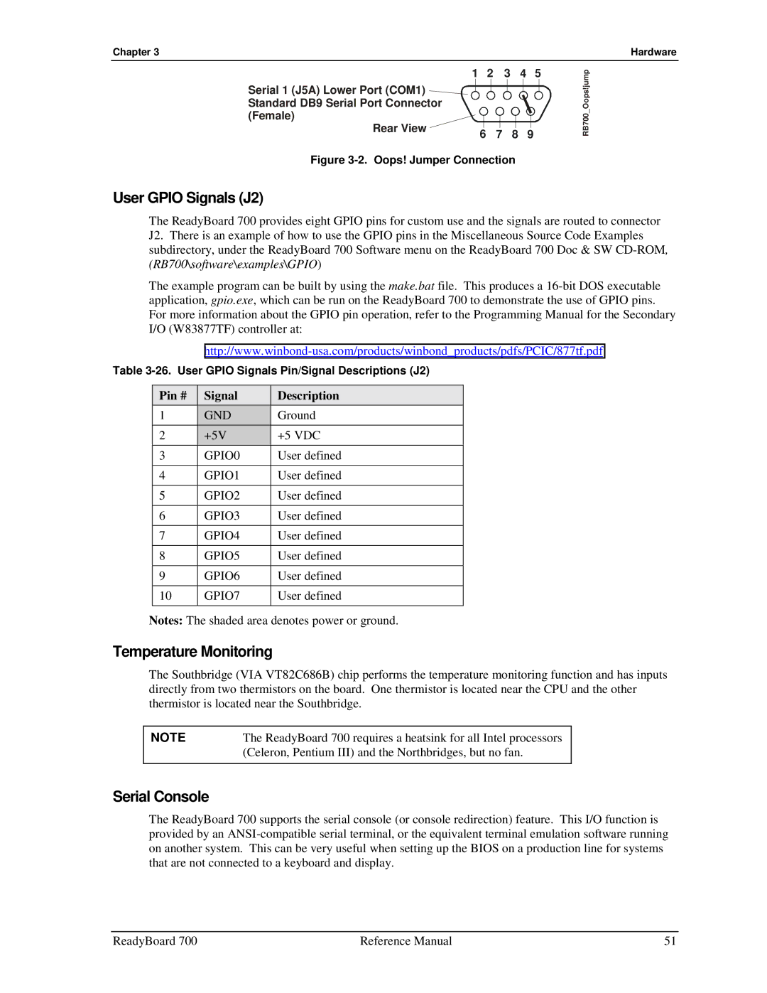
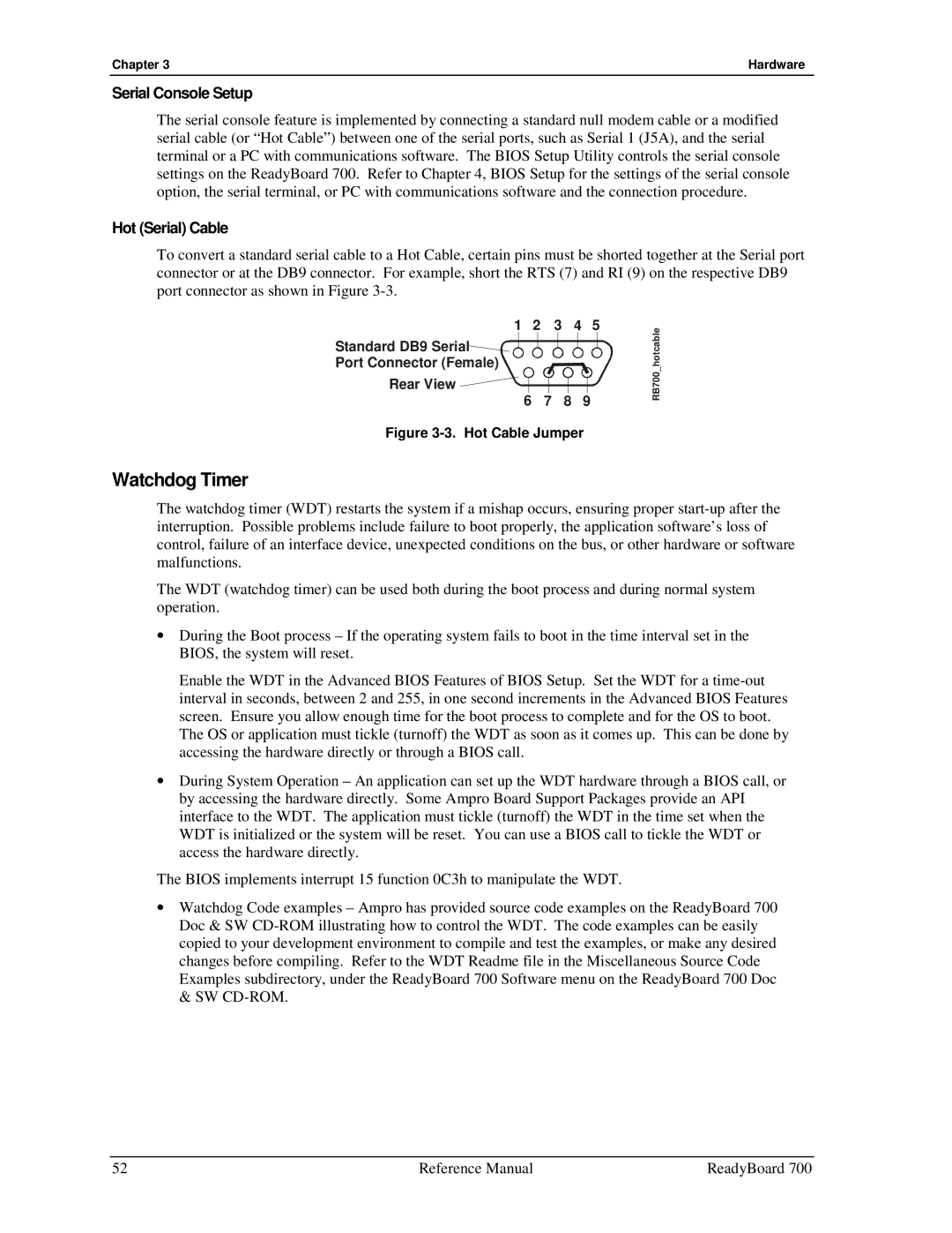
To convert a standard serial cable to a Hot Cable, certain pins must be shorted together at the Serial port connector or at the DB9 connector. For example, short the RTS (7) and RI (9) on the respective DB9 port connector as shown in Figure 3-3.

1 2 3 4 5

Standard DB9 Serial Port Connector (Female)

Rear View 6 7 8 9

Figure 3-3. Hot Cable Jumper

RB700_hotcable

Watchdog Timer

The watchdog timer (WDT) restarts the system if a mishap occurs, ensuring proper start-up after the interruption. Possible problems include failure to boot properly, the application software’s loss of control, failure of an interface device, unexpected conditions on the bus, or other hardware or software malfunctions.

The WDT (watchdog timer) can be used both during the boot process and during normal system operation.

During the Boot process – If the operating system fails to boot in the time interval set in the BIOS, the system will reset.

Enable the WDT in the Advanced BIOS Features of BIOS Setup. Set the WDT for a time-out interval in seconds, between 2 and 255, in one second increments in the Advanced BIOS Features screen. Ensure you allow enough time for the boot process to complete and for the OS to boot. The OS or application must tickle (turnoff) the WDT as soon as it comes up. This can be done by accessing the hardware directly or through a BIOS call.

During System Operation – An application can set up the WDT hardware through a BIOS call, or by accessing the hardware directly. Some Ampro Board Support Packages provide an API interface to the WDT. The application must tickle (turnoff) the WDT in the time set when the WDT is initialized or the system will be reset. You can use a BIOS call to tickle the WDT or access the hardware directly.

The BIOS implements interrupt 15 function 0C3h to manipulate the WDT.

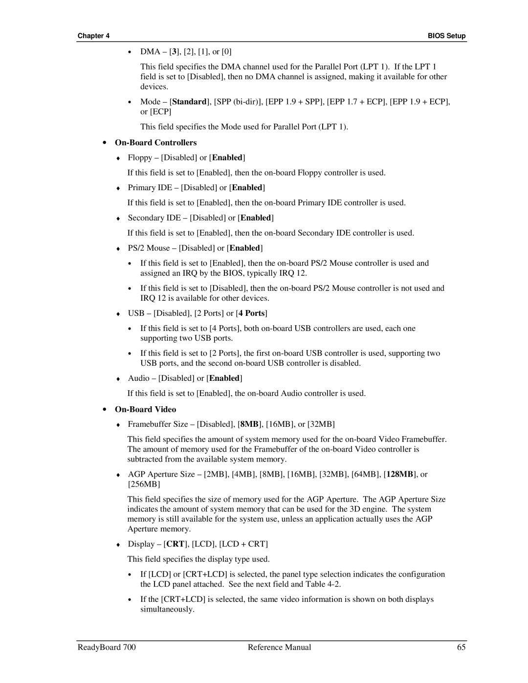
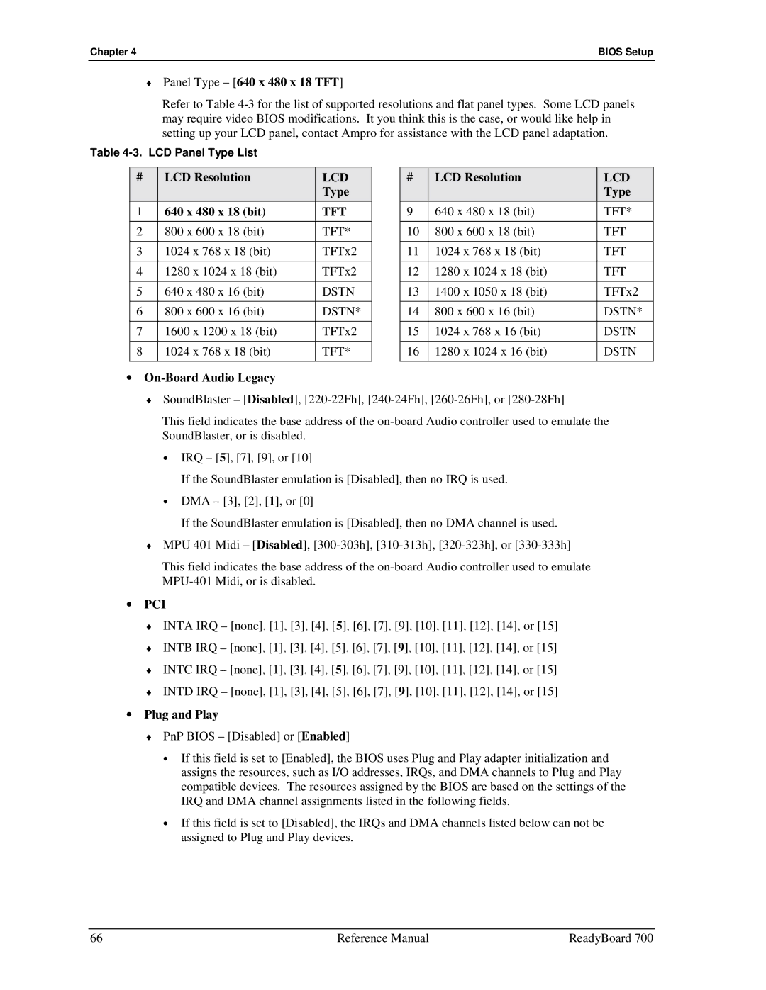
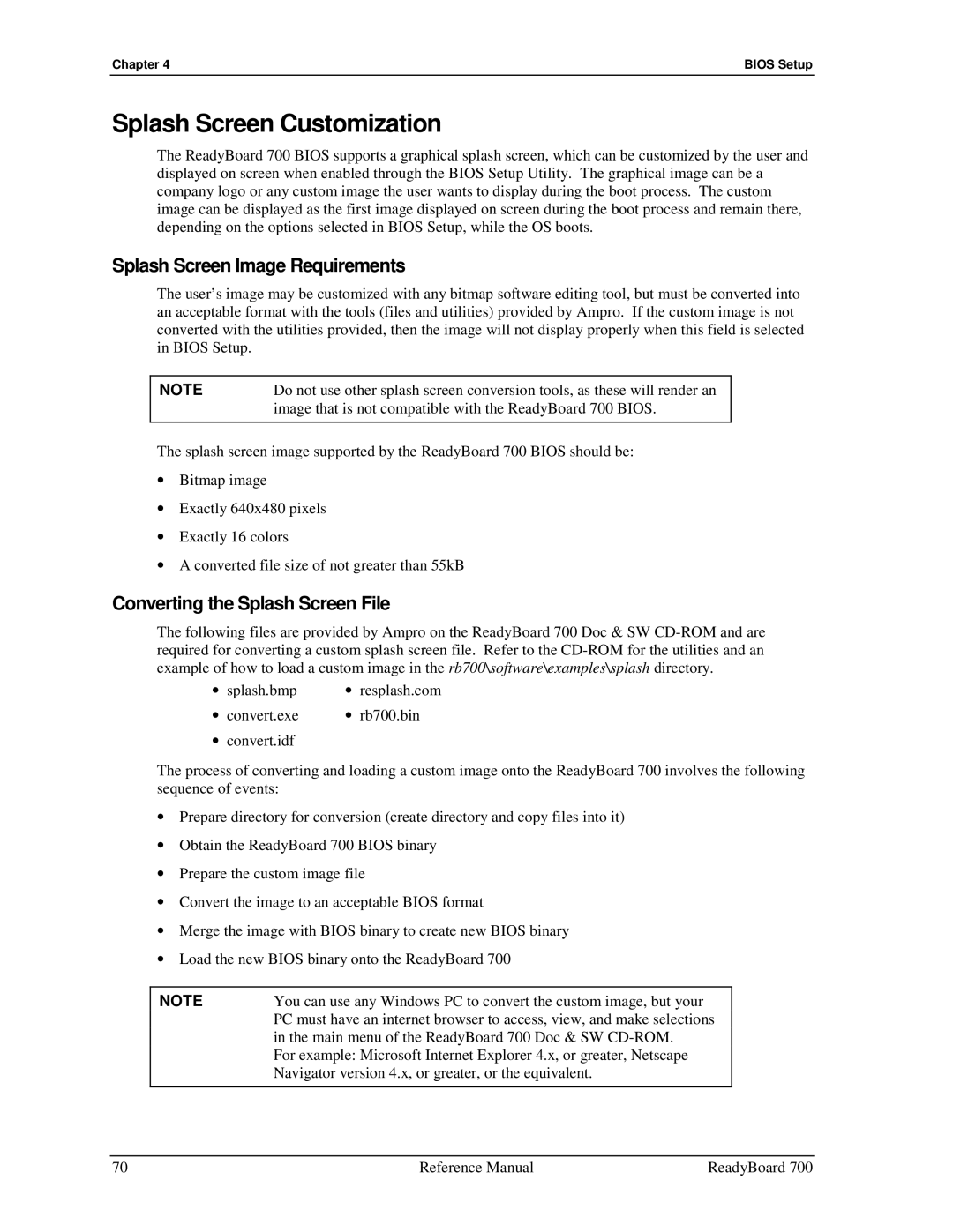
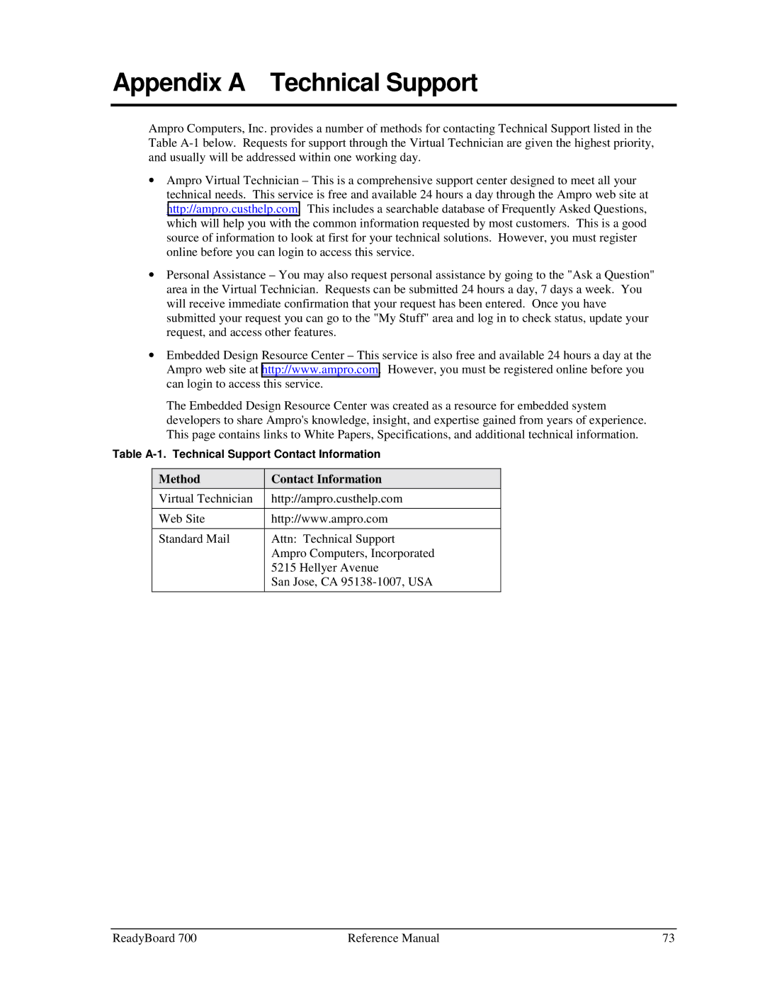
Watchdog Code examples – Ampro has provided source code examples on the ReadyBoard 700 Doc & SW CD-ROM illustrating how to control the WDT. The code examples can be easily copied to your development environment to compile and test the examples, or make any desired changes before compiling. Refer to the WDT Readme file in the Miscellaneous Source Code Examples subdirectory, under the ReadyBoard 700 Software menu on the ReadyBoard 700 Doc & SW CD-ROM.

52

Reference Manual

ReadyBoard 700

Image 58
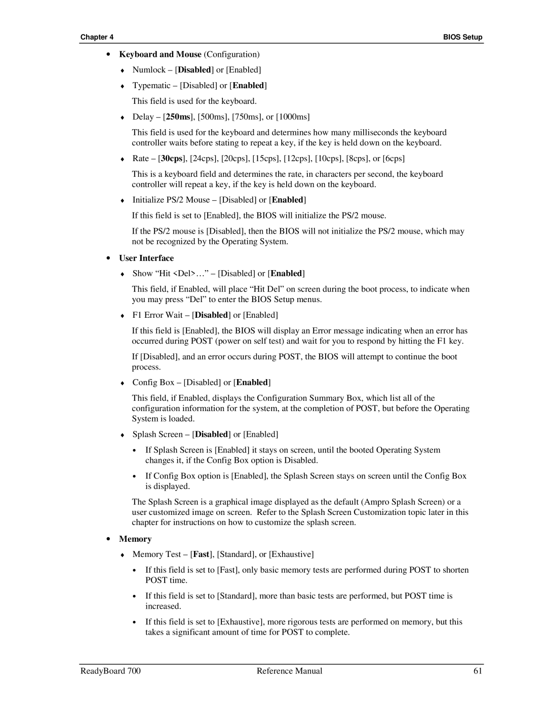
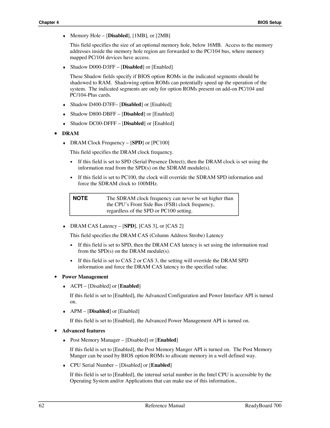
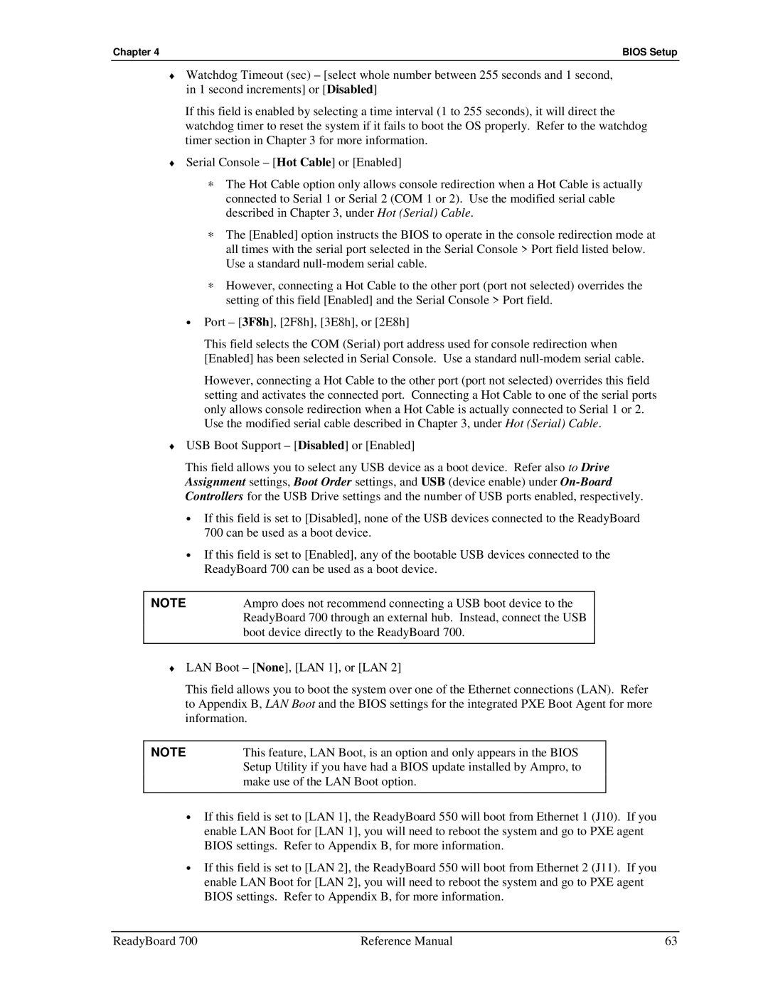
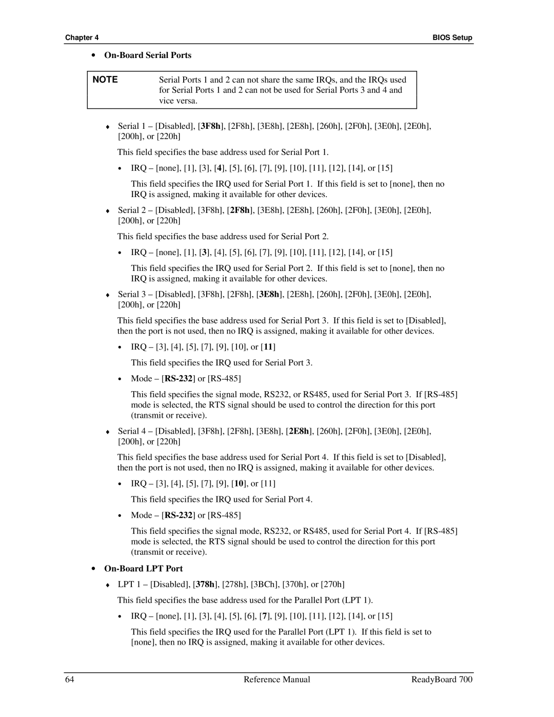
Contents ReadyBoard Single Board Computer Reference Manual Audience Assumptions Revision HistoryContents Appendix a List of Tables Reference Manual ReadyBoard Purpose of this Manual SpecificationsReference Material Other ReadyBoard Products Related Ampro ProductsReadyBoard 700 Support Products Other Ampro ProductsChapter Reference Manual ReadyBoard Product Overview Epic ArchitectureBoard Features Product DescriptionChapter Chapter Block Diagram ATACPU Major Integrated Circuits ICsChip Type Mfg Model Description Function VIAJack # Signal/Device Description Connector DefinitionsSwitch Definition Component DescriptionAll illustrations Lvds J7Additional Components IllustrationsIndicator Definition Power/IDE LED DefinitionsJumper # Installed Removed Jumper DefinitionsJumper, Switch, and LED Locations Top view Power Specifications SpecificationsPhysical Specifications Environmental SpecificationsMechanical Specifications Thermal/Cooling RequirementsReadyBoard 700 Side view Chapter Hardware OverviewSdram Memory DIMM1 CPU U4Memory Flash MemoryInterrupt Channel Assignments Memory MapAddress hex Subsystem Address MapBase Address Function CF8-CFFPin # Signal Input Description Output PC/104-Plus Interface J12CLK2 REQ0GNT1 PerrIntd REQ2CLK0 IntaGNT2 IDSEL1REQ1 CLK3GNT0 IDSEL2IDSEL3 CLK1Pin # Signal Description J13 Row a PC/104 Interface J13 A/B, J14 C/DPin # Signal Descriptions J13 Row B Pin # Signal Descriptions J14 Row C Pin # Signal Descriptions J14 Row D DRQ5 DRQ0DACK5 DACK6Pin # Signal Description IDE Interface J22Pdiordy PdiowPdior PdcselCompactFlash Adapter J23 SDD11 CFD2CFD1 SDD12Floppy/Parallel Interface J20 Autofdx SlctinStep DrvenoSerial Interfaces J5A/B, J3A/B RS485 Serial Port ImplementationSerial a Interface J5A/B Serial B Interface J3A/B CTS4 DTR4Primary USB0 and USB1 J15A/B USB Interfaces J15A/B, J21A/BSecondary USB2 and USB3 J21A/B Pin # Ethernet Interfaces J10, J11Digital Ground Audio Interface J19 Video Interfaces J8, J9, J7 CRT Interface J8LCD Interface J9 Pin # Signal Description Line Channel Lvds Interface J7Utility Interface J18 Reset Switch SW1Miscellaneous Keyboard/Mouse Interface J16Real Time Clock RTC Oops! Jumper Bios RecoveryInfrared IrDA Port J17 IrtxTemperature Monitoring User Gpio Signals J2Serial Console Watchdog Timer Serial Console SetupPower-On Interface J6 Power Interfaces J4, J6Power In Interface J4 VccsbReference Manual ReadyBoard Accessing Bios Setup VGA Display IntroductionAccessing Bios Setup Serial Console Bios Setup Menu Item/TopicBios Menus Bios Setup Opening ScreenDate & Time Bios Configuration ScreenDrive Assignments # of Floppy Drives Bios Settings Boot OrderDrive and Boot Options User Interface Keyboard and Mouse ConfigurationMemory Power Management Advanced featuresChapter Bios Setup On-Board Serial Ports On-Board LPT PortOn-Board Controllers On-Board VideoType LCD ResolutionPanel Type 640 x 480 x 18 TFT 640 x 480 x 18 bitChapter Bios Setup Chapter Bios Setup Chapter Bios Setup Splash Screen Image Requirements Splash Screen CustomizationConverting the Splash Screen File \splashconvert convert.idf Reference Manual ReadyBoard Appendix a Technical Support Method Contact InformationAppendix a Appendix B LAN Boot Option PXE Boot Agent Bios Setup Accessing PXE Boot Agent Bios SetupPXE Configuration PXE Boot Agent Setup ScreenTCP/IP Configuration NetWare Configuration RPL ConfigurationCD-ROM LEDRTC PostWatchdog timer WDT Table notes Reference Manual ReadyBoard