Novatel OM-20000122 Configuring Span with Align on SPAN-CPT, Chapter SPAN-CPT Dual-Antenna

Page 38

Chapter 4


SPAN-CPT Dual-Antenna


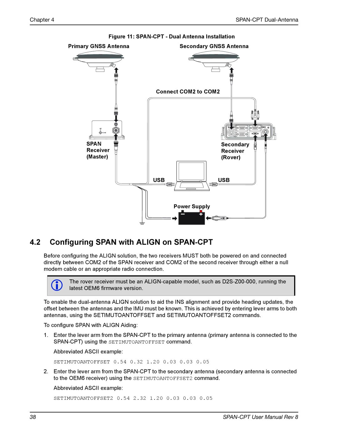
Figure 11: SPAN-CPT - Dual Antenna Installation

Primary GNSS Antenna

Secondary GNSS Antenna


Connect COM2 to COM2

COM 1

I/O

COM 2

SPAN

Secondary

Receiver

Receiver

(Master)

(Rover)

USB

USB


Power Supply

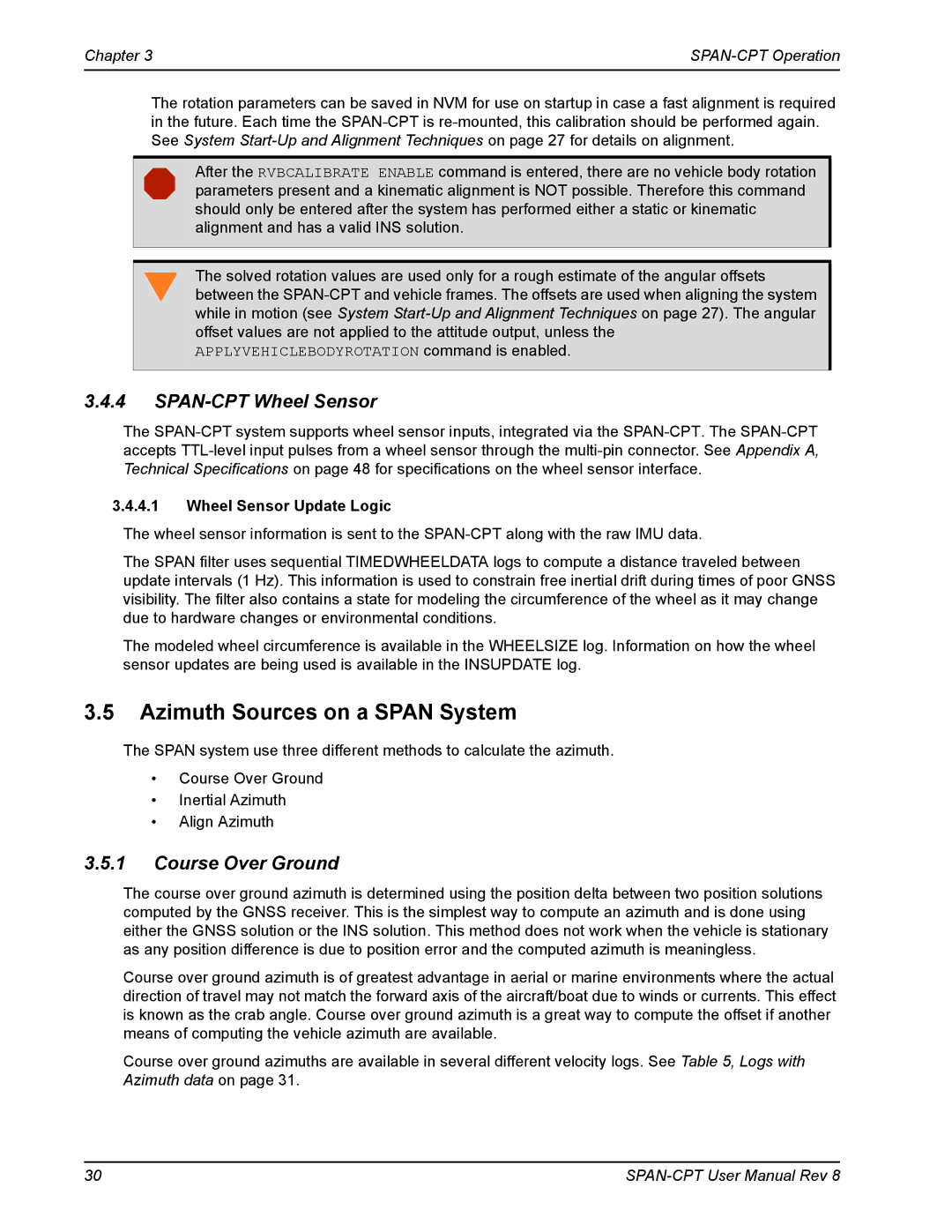
4.2Configuring SPAN with ALIGN on SPAN-CPT

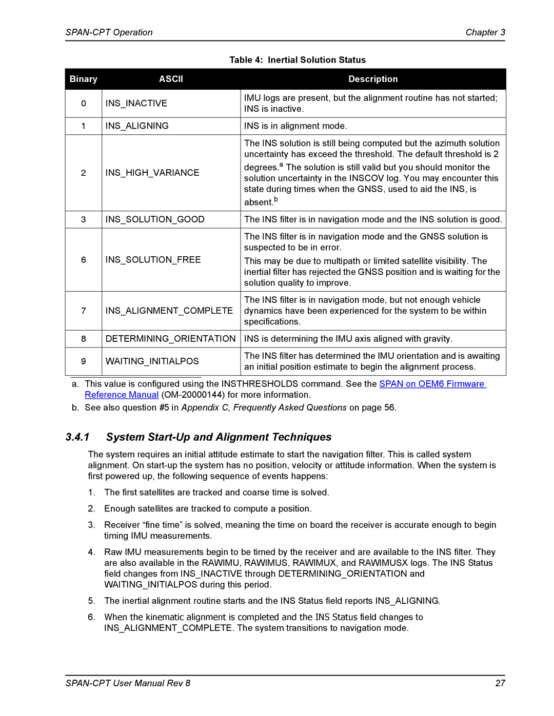
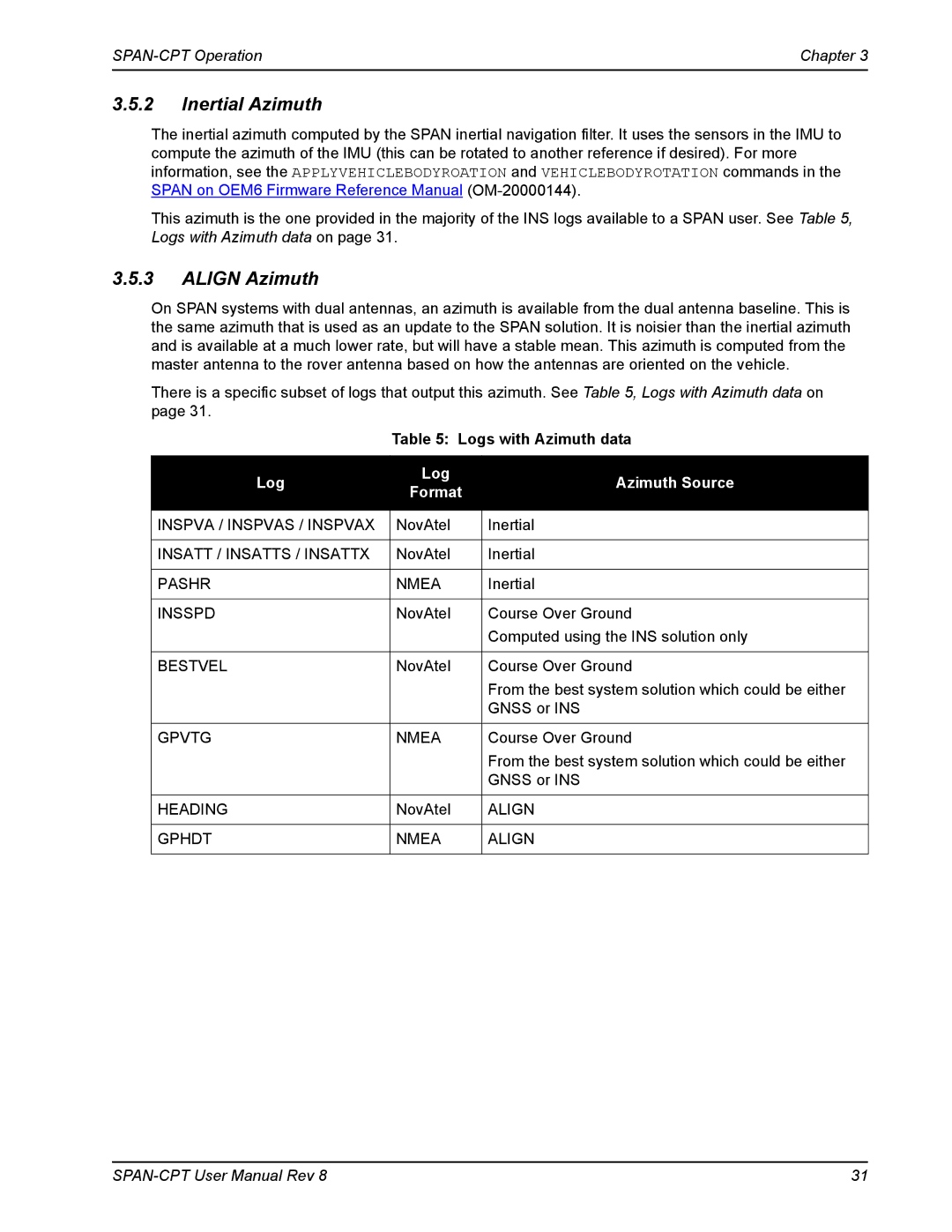
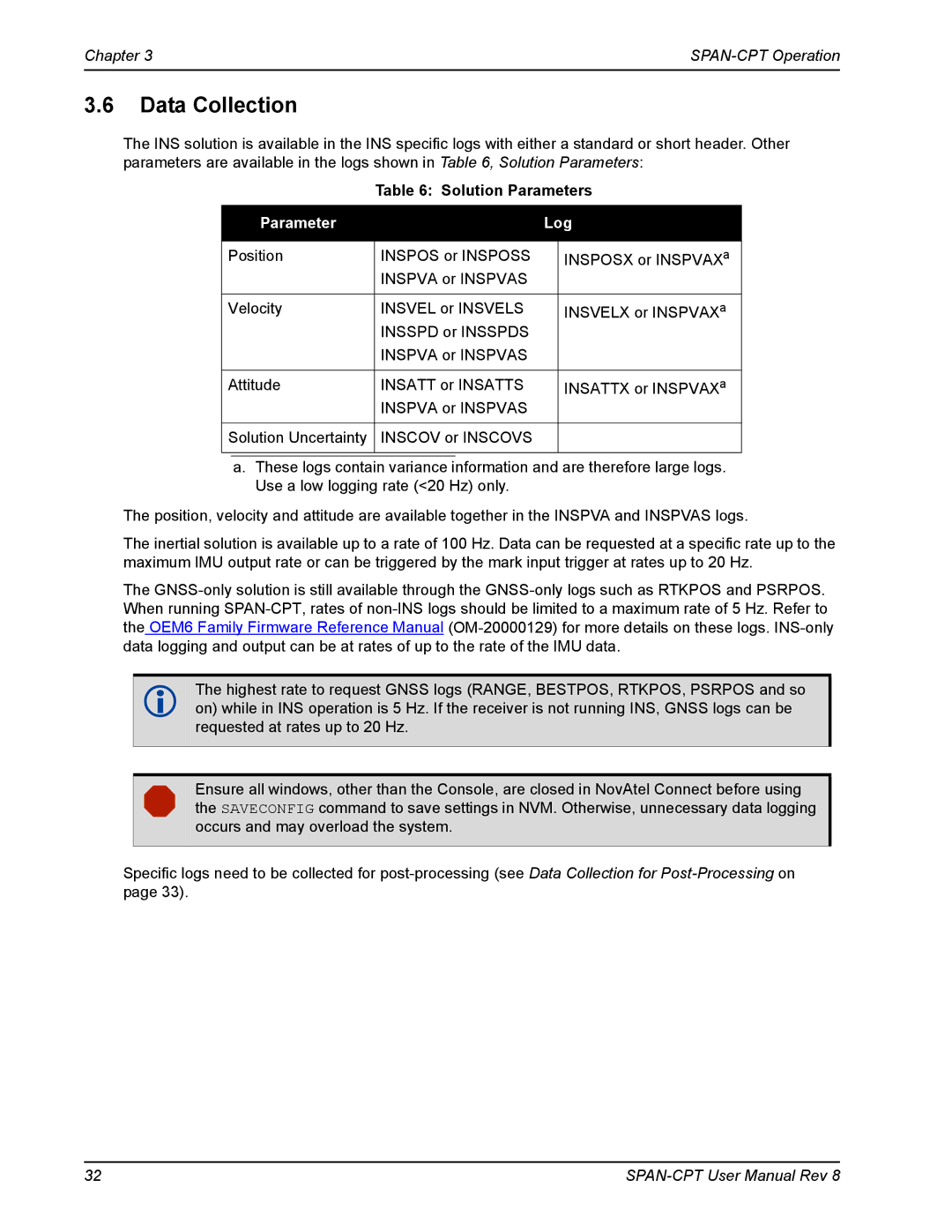
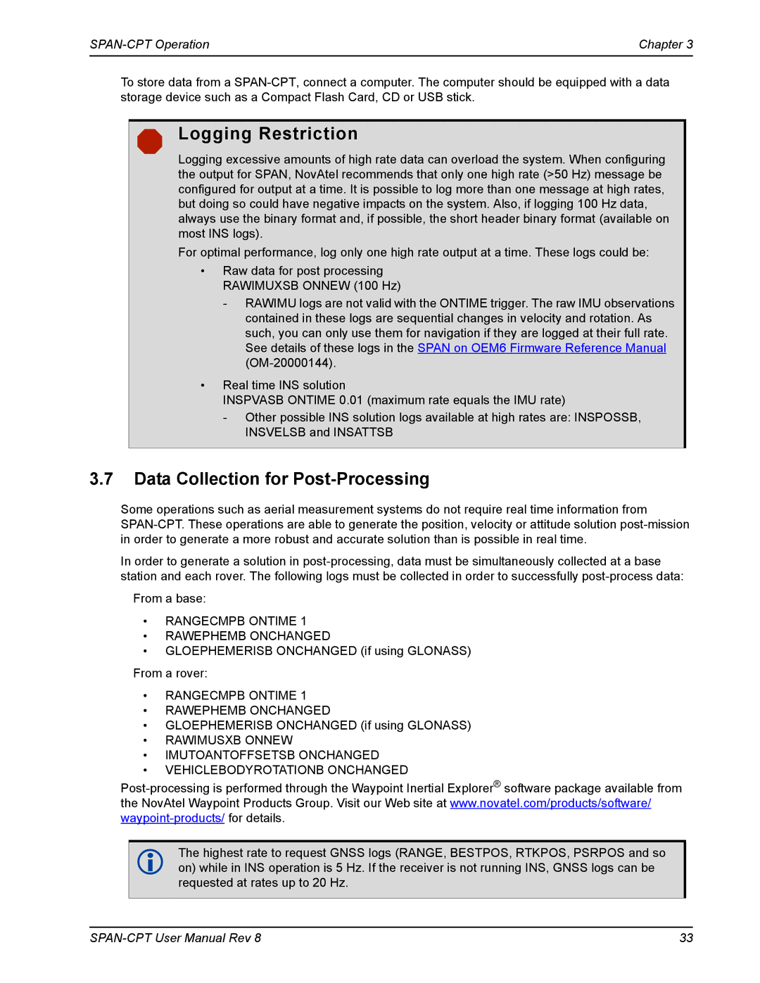
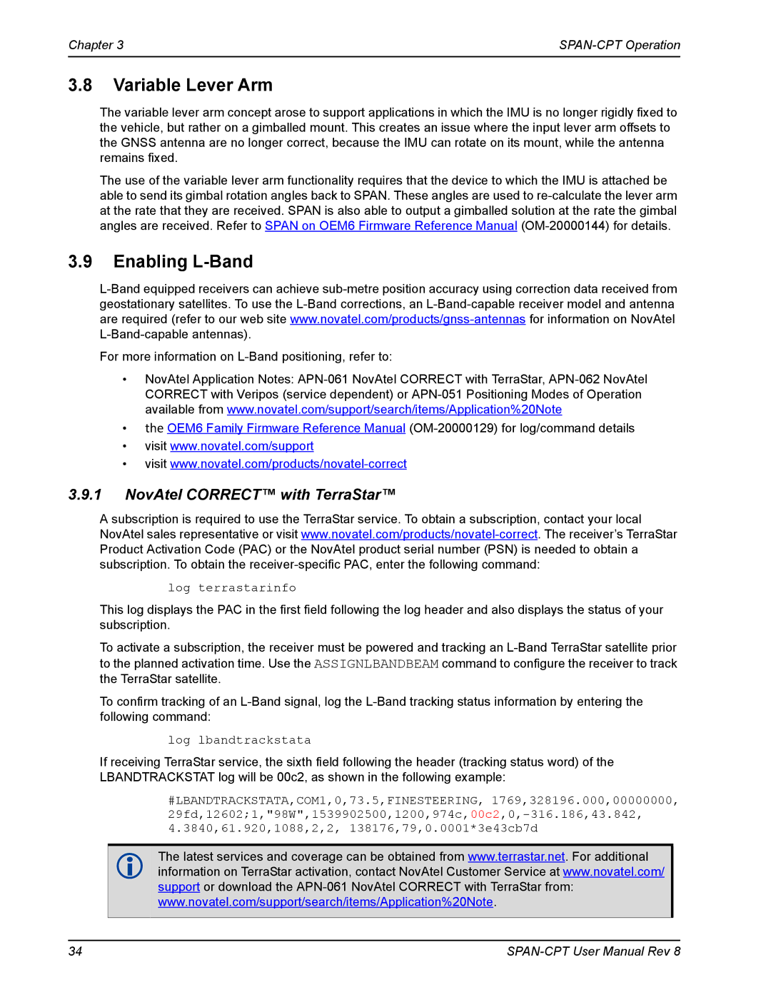
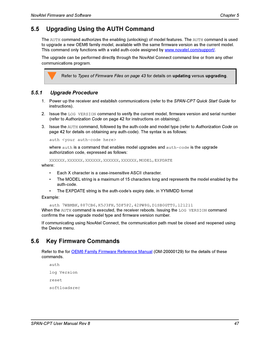
Before configuring the ALIGN solution, the two receivers MUST both be powered on and connected directly between COM2 of the SPAN receiver and COM2 of the second receiver through either a null modem cable or an appropriate radio connection.

The rover receiver must be an ALIGN-capable model, such as D2S-Z00-000, running the latest OEM6 firmware version.

To enable the dual-antenna ALIGN solution to aid the INS alignment and provide heading updates, the offset between the antennas and the IMU must be known. This is achieved by entering lever arms to both antennas, using the SETIMUTOANTOFFSET and SETIMUTOANTOFFSET2 commands.

To configure SPAN with ALIGN Aiding:

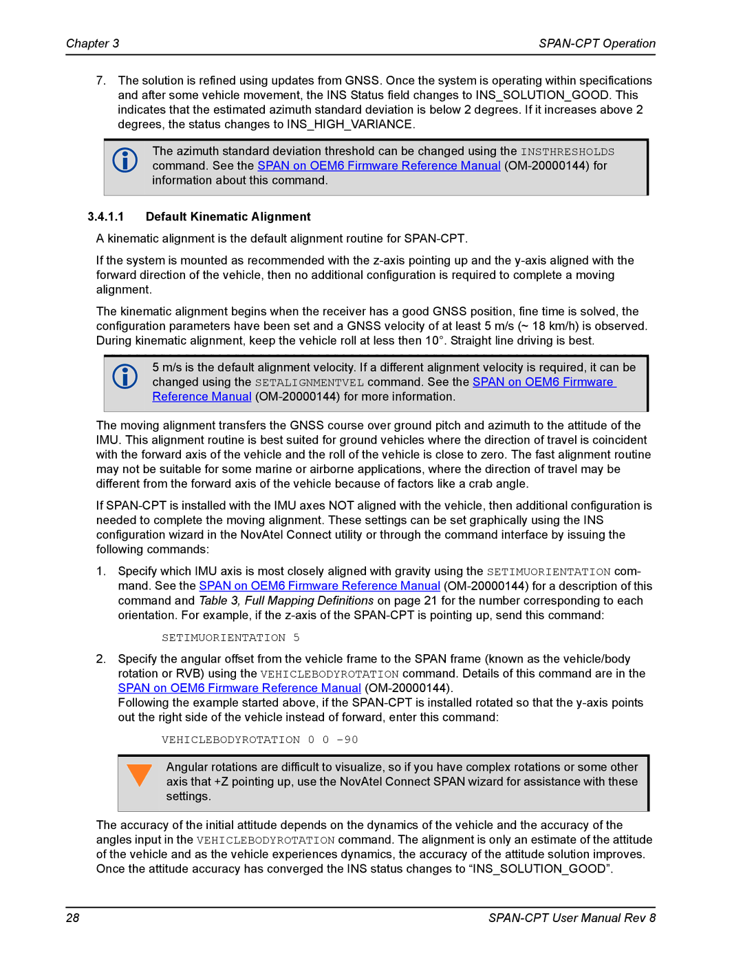
1.Enter the lever arm from the SPAN-CPT to the primary antenna (primary antenna is connected to the SPAN-CPT) using the SETIMUTOANTOFFSET command.

Abbreviated ASCII example:

SETIMUTOANTOFFSET 0.54 0.32 1.20 0.03 0.03 0.05

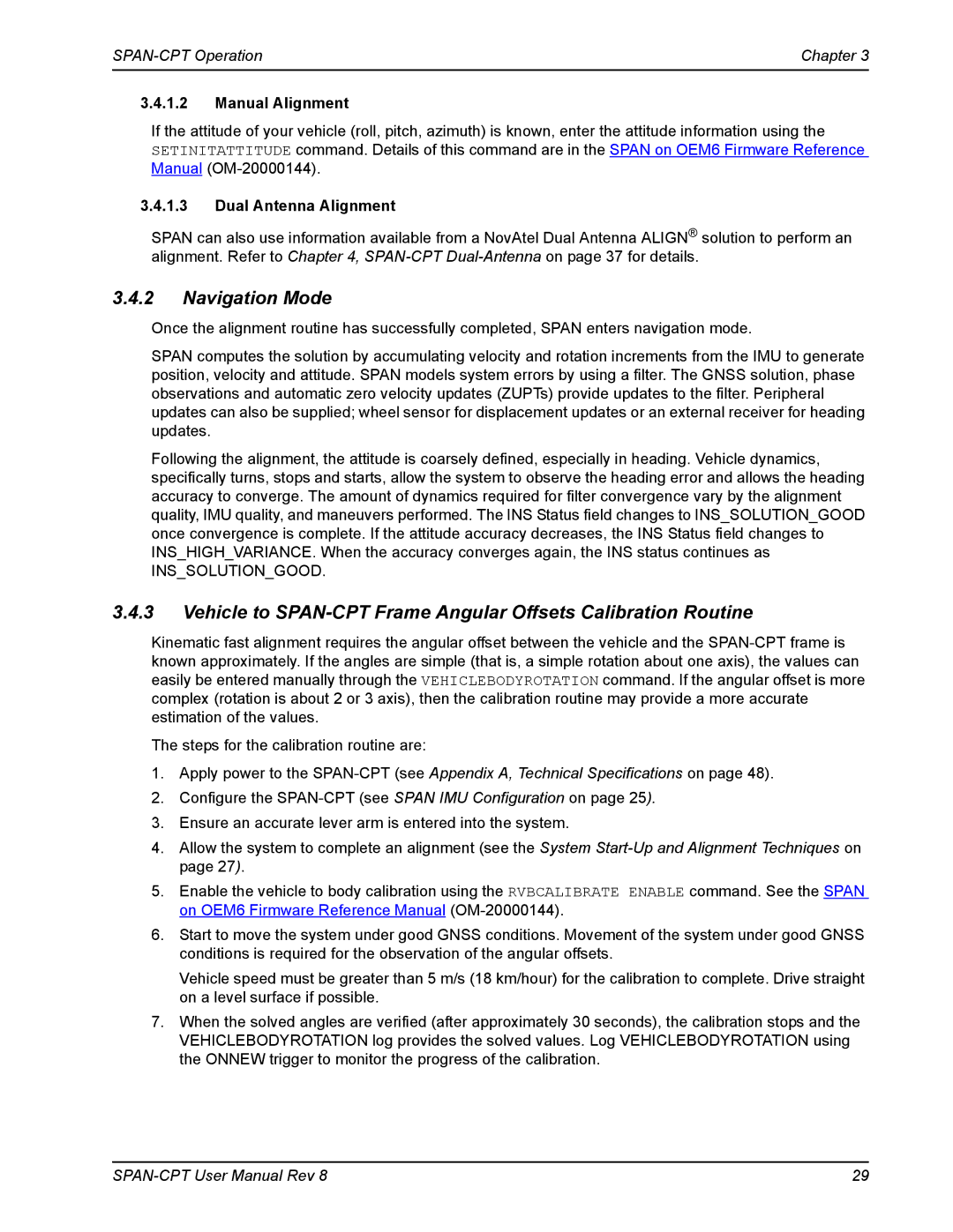
2.Enter the lever arm from the SPAN-CPT to the secondary antenna (secondary antenna is connected to the OEM6 receiver) using the SETIMUTOANTOFFSET2 command.

Abbreviated ASCII example:

SETIMUTOANTOFFSET2 0.54 2.32 1.20 0.03 0.03 0.05

38

SPAN-CPT User Manual Rev 8

Image 38
Contents SPAN-CPT Warranty Return instructions Proprietary NoticeTable of Contents Technical Specifications Figures Tables NovAtel Knowledge Base Before Contacting Customer Support Contact InformationCE Notice FCC NoticesIndustry Canada Weee Notice Lightning Protection Installation and Grounding ProcedureWhat is the hazard? Hazard ImpactPrimary and Secondary Lightning Protection Ref # Description Introduction Fundamentals of GNSS+INSConventions System ComponentsRelated Documents and Information Manuals SPAN-CPT InstallationRequired Equipment SPAN-CPT HardwareHardware Set Up Typical SPAN-CPT Set Up Radio COM2Mount the Antenna Mount the SPAN-CPTConnect Power Connect the Gnss AntennaConnect a Computer to the SPAN-CPT Connect the I/O Strobe SignalsBattery Isolator Auxiliary Vehicle MainBattery Odometer Requirements Can BusOdometer Connection Cable Modification for Kistler WPT Cable Cable Modification for SPAN-CPT CableLocal Level Frame SPAN-CPT OperationDefinition of Reference Frames Within Span Span Body Frame Full Mapping DefinitionsEnclosure Frame Vehicle FrameCommunicating with the SPAN-CPT System Use NovAtel Connect to CommunicateChapter SPAN-CPT Operation Span IMU Configuration Software ConfigurationGnss Configuration SPAN-CPT Configuration with NovAtel ConnectReal Time Operation System Start-Up and Alignment Techniques AsciiDefault Kinematic Alignment SetimuorientationDual Antenna Alignment Navigation ModeManual Alignment Course Over Ground Wheel Sensor Update LogicAzimuth Sources on a Span System Logs with Azimuth data Inertial AzimuthAlign Azimuth Solution Parameters Data Collection Logging Restriction Data Collection for Post-ProcessingNovAtel Correct with TerraStar Variable Lever ArmEnabling L-Band Veripos Marine Subscriptions OmniSTARChapter SPAN-CPT Operation Installation SPAN-CPT Dual-AntennaChapter SPAN-CPT Dual-Antenna Configuring Span with Align on SPAN-CPTPower Supply SecondaryUnaided Alignment Alignment on a Moving Vessel Aided Transfer AlignmentAlignment on a Stationary Vehicle Aided Static Alignment Span Align Attitude Updates Automatic Alignment Mode Automatic Alignment defaultNovAtel Firmware and Software Firmware Updates and Model UpgradesFirmware Updates Authorization Code Model UpgradesTypes of Firmware Files Updating or Upgrading Using the WinLoad UtilityTransferring Firmware Files Using the WinLoad Utility Open a File to DownloadUpdating using SoftLoad Commands Searching for CardWorking with S-Records Softloadsrec S-RECORDUpgrade Procedure Upgrading Using the Auth CommandKey Firmware Commands Hardware Specification for SPAN-CPT Technical SpecificationsSPAN-CPT Technical Specifications KVH IMU Sensor SpecificationsElectrical and Environmental Specifications Power SpecificationsSPAN-CPT Mechanical Drawings SPAN-CPT Side and Perspective ViewSPAN-CPT Top, Front and Bottom View SPAN-CPT Cable SPAN-CPT 60723108 KVH Development Terminated Cable Pin-OutFemale Male Pin Function Wire Pair Wire Color SPAN-CPT 60723107 KVH Standard Un-terminated Cable Pin-OutSPAN-CPT System Replacement PartsAccessories and Options Frequently Asked Questions Appendix COM-20000122 Rev March