Woodstock W1772, W1773 owner manual Bearing Replacement, To align the pulleys, do these steps

Page 36

W1772/W1773 37" Drum Sander

Each pulley can be adjusted by loosening the set screw that secures the pulley to the shaft, sliding the pulley in/ out, and retightening the set screw to lock the pulley in place.

To align the pulleys, do these steps:

1.DISCONNECT POWER TO THE SANDER!

2.Remove the table height handwheel, open the pulley cover, and remove the V-belts.

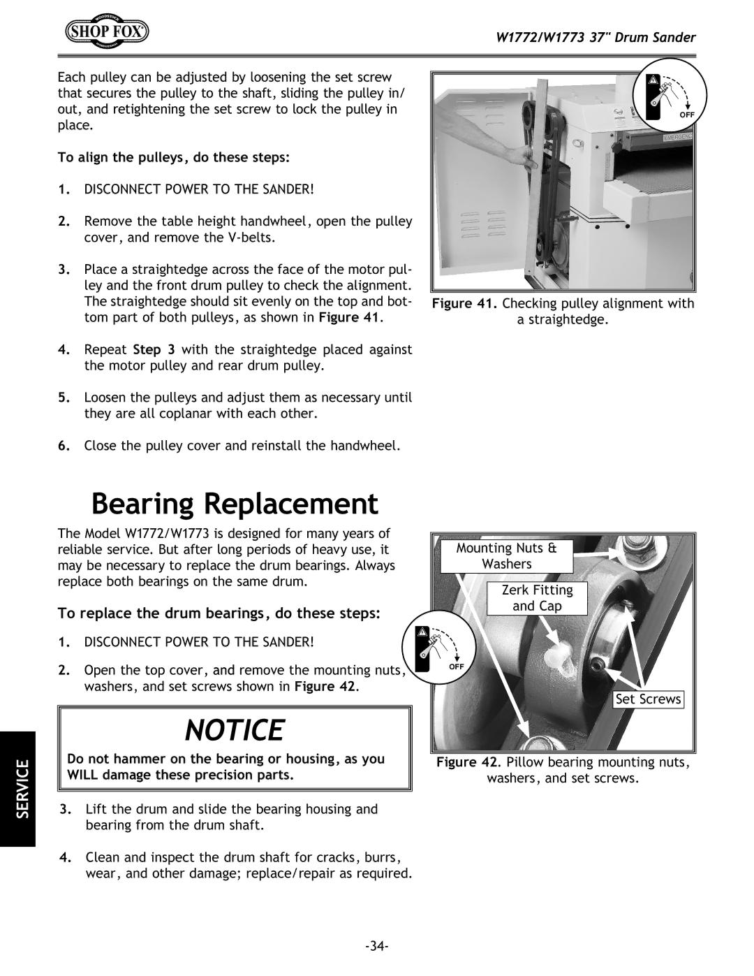
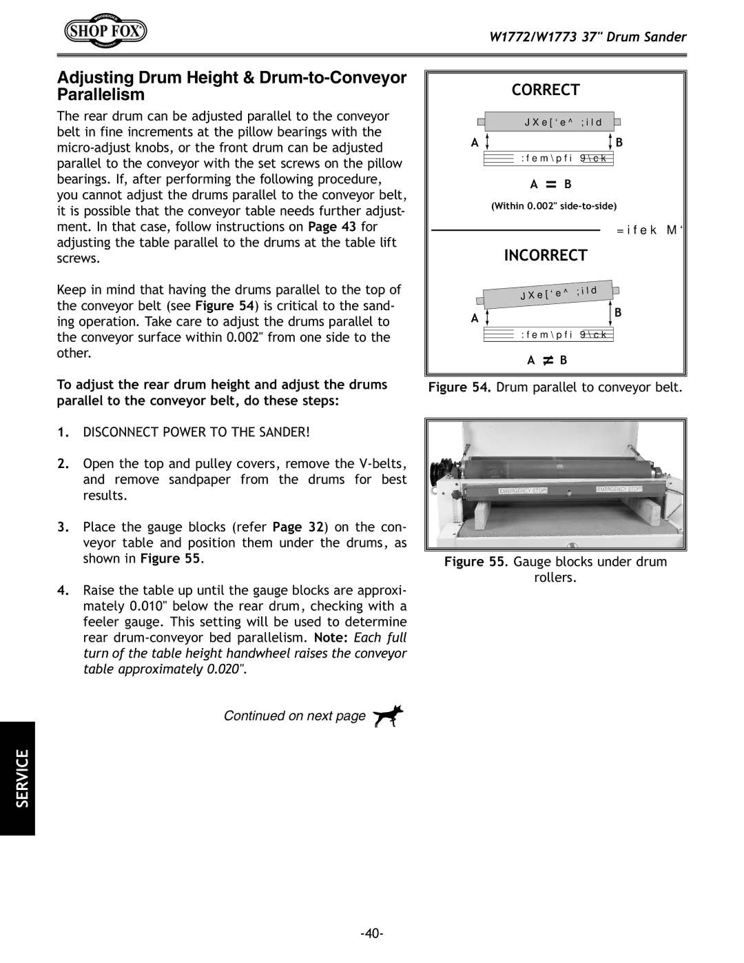
3.Place a straightedge across the face of the motor pul- ley and the front drum pulley to check the alignment. The straightedge should sit evenly on the top and bot- tom part of both pulleys, as shown in Figure 41.

4.Repeat Step 3 with the straightedge placed against the motor pulley and rear drum pulley.

5.Loosen the pulleys and adjust them as necessary until they are all coplanar with each other.

OFF

Figure 41. Checking pulley alignment with

a straightedge.

6.Close the pulley cover and reinstall the handwheel.

SERVICE

Bearing Replacement

The Model W1772/W1773 is designed for many years of reliable service. But after long periods of heavy use, it may be necessary to replace the drum bearings. Always replace both bearings on the same drum.

To replace the drum bearings, do these steps:

1. DISCONNECT POWER TO THE SANDER!

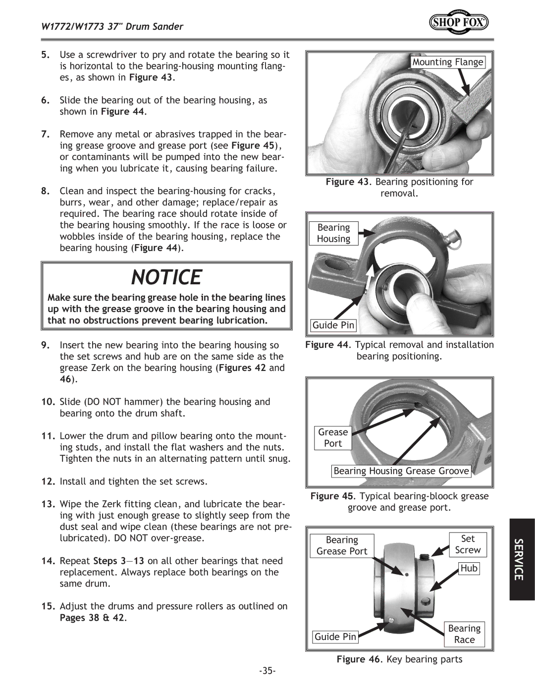
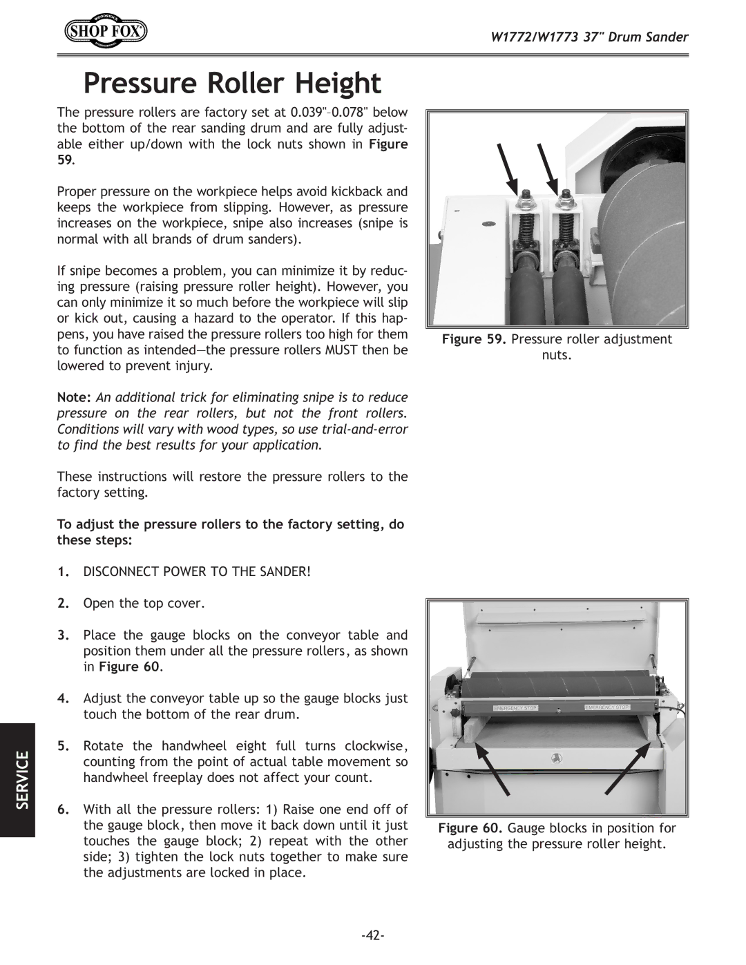
2.Open the top cover, and remove the mounting nuts, washers, and set screws shown in Figure 42.

NOTICE

Do not hammer on the bearing or housing, as you WILL damage these precision parts.

3.Lift the drum and slide the bearing housing and bearing from the drum shaft.

4.Clean and inspect the drum shaft for cracks, burrs, wear, and other damage; replace/repair as required.

Mounting Nuts &

Washers

Zerk Fitting

and Cap

OFF

Set Screws

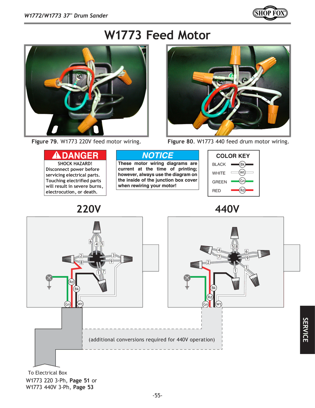
Figure 42. Pillow bearing mounting nuts,

washers, and set screws.

-34-

Image 36
Contents Drum Sander Page Contents Introduction Woodstock Technical SupportIntroduction Introduction Introduction Introduction Controls and Features Safety Standard Safety InstructionsAlways Lock Mobile Bases if Used Before Operating Machinery Additional Safety for Drum Sanders W1772 Single-Phase Operation W1772 Electrical SpecificationsElectrical W1773 220V/440V Phase Operation Phase ConverterW1773 Electrical Specifications Rewiring W1773 to To rewire the Model W1773 for 440V operation, do these stepsSetup Items Needed for SetupUnpacking InventoryAssembly If you do not hear any scraping sounds go to StepControl panel mounting bolts Machine Placement W1772/W1773 minimum working clearancesLifting Sander Mounting to Shop FloorTo place the sander in a permanent location, do these steps Power Connection To connect the sander to the power source, do these stepsDust Collection Recommended CFM at SanderGear Oil Check To check the gear oil, do these stepsTest Run To test run the drum sander, do these stepsRecommended Adjustments SETOperations Control PanelGeneral Sanding Drums Start Button Starts the sanding drumsTo adjust the conveyor speed, do these steps Depth of CutVariable Speed To set the depth of cut, do these stepsUsing the Amp Draw Meter SandingTo sand a workpiece, do these steps Sanding Tips Choosing Sandpaper Grit ClassPaper Replacement To change the paper, do these stepsDrum Sander Accessories Maintenance CleaningLubrication Step Lubricating gear boxService Gauge BlocksTo make the gauge blocks, do these steps Belt Service To adjust V-belt tension, do these stepsBearing Replacement To align the pulleys, do these stepsThat no obstructions prevent bearing lubrication Pages 38Conveyor Tensioning Tracking To tension the conveyor, do these stepsTracking To track the conveyor, do these stepsDrum Adjustments Adjusting Drums Perpendicular to Feed DirectionFront and rear drum Adjustment locations Loosen the front drum pillow bearing lock nuts FigureAdjusting Drum Height & Drum-to-Conveyor Parallelism Rear right sanding drum micro Adjusting knob Loosen the front drum pillow bearing lock nuts ,Pressure roller adjustment Nuts Pressure Roller HeightTo adjust a dust scoop, do these steps Scale Pointer CalibrationDust Scoops Table Lift ScewsTo adjust the table lift screws, do these steps Marking sprocket tooth ChainW1772/W1773 Wiring Overview Emergency stop bar limit SwitchW1772/W1773 control panel wiring W1772/W1773 Control PanelW1772 Electrical Box 220V, 1-Ph W1772 electrical boxW1772 Electrical Box Wiring 220V, 1-Ph FiguresW1772 sanding drum motor Wiring and start capacitors W1772 Sanding & Feed MotorsW1773 Electrical Box 220V, 3-Phase W1773 Electrical Box Wiring 220V, 3-Phase FiguresW1773 Electrical Box 440V, 3-Phase W1773 440V 3-phase electrical box wiringW1773 Electrical Box Wiring 440V, 3-Phase Figures 66W1773 220V sanding drum motor Wiring W1773 Sanding Drum MotorW1773 220V feed motor wiring W1773 Feed MotorTroubleshooting Moving parts have come to a complete stopMachine Operations Parts Frame Parts BreakdownFrame Parts List PART# DescriptionParts Breakdown Conveyor Parts List Roller & Drum Parts Breakdown XPK55MMicro-Adjustment Breakdown Electrical Components Electrical Parts List CurrentsensorLabel Placement Warranty Registration CommentsBOX BELLINGHAM, WA Warranty