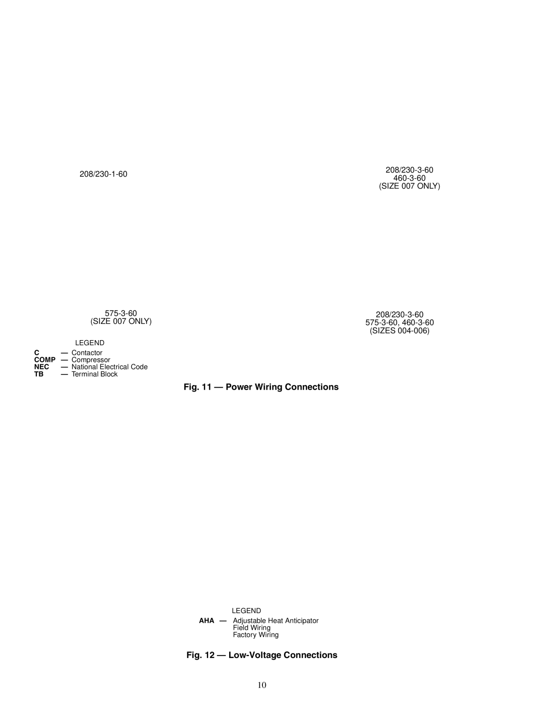
Carrier 48TJE, TJF004, TJF005-007, 48TJD specifications Unit Leveling Tolerances

Page 4

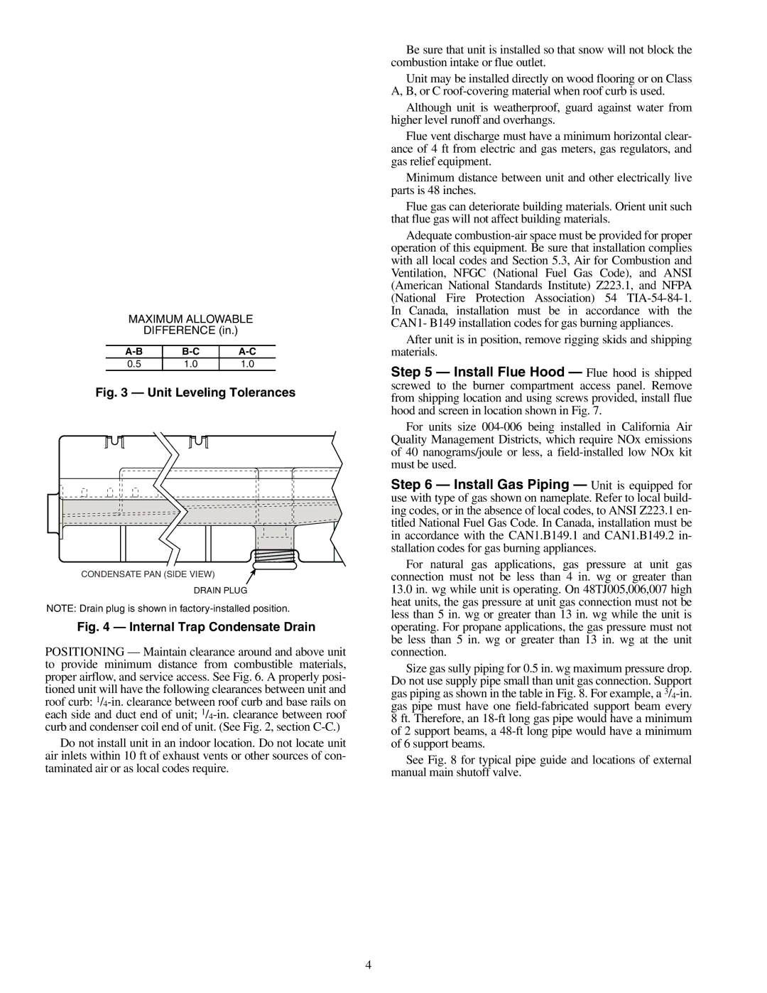
MAXIMUM ALLOWABLE

DIFFERENCE (in.)

A-B

B-C

A-C

0.5

1.0

1.0

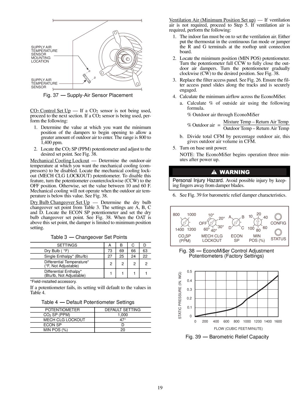
Fig. 3 — Unit Leveling Tolerances

CONDENSATE PAN (SIDE VIEW)

DRAIN PLUG

NOTE: Drain plug is shown in factory-installed position.

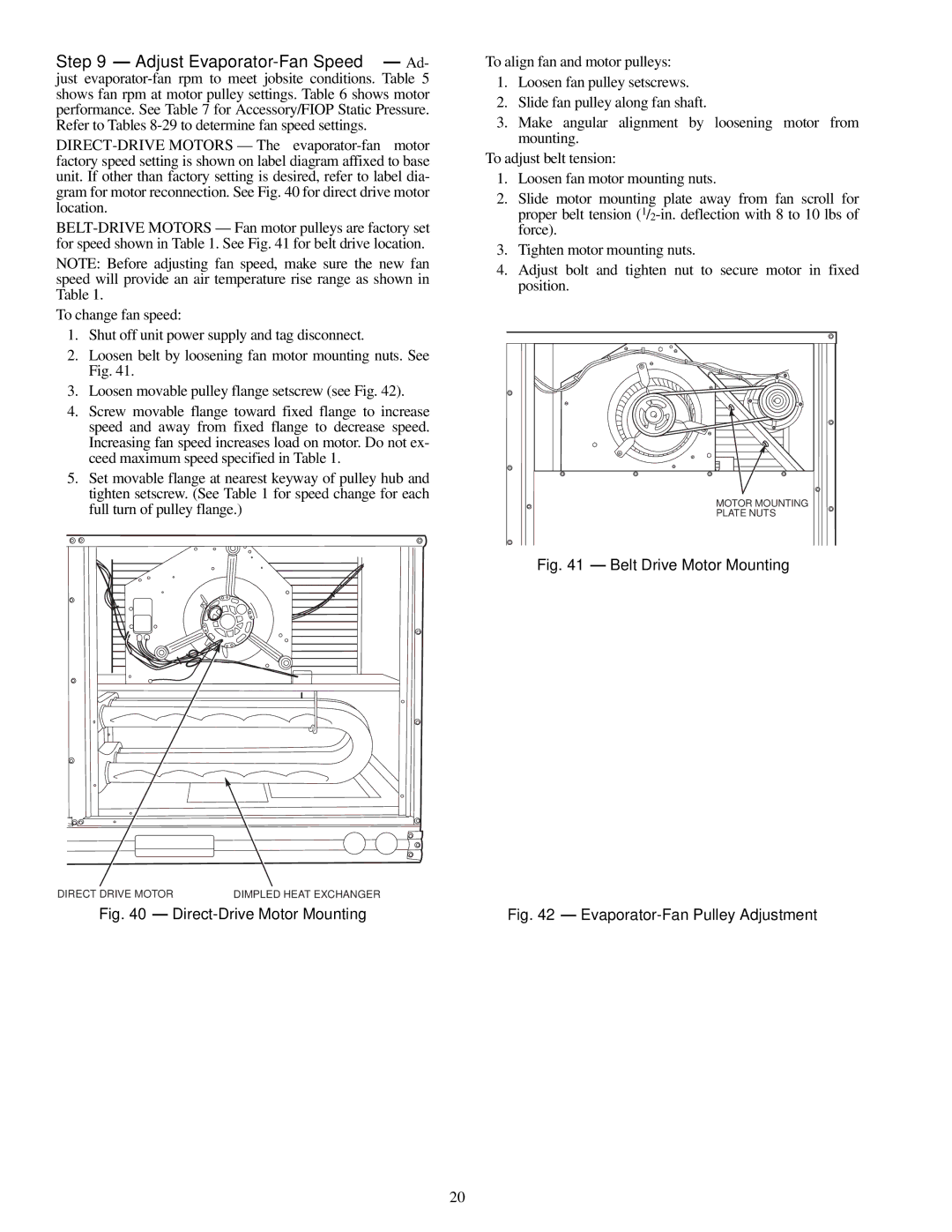
Fig. 4 — Internal Trap Condensate Drain

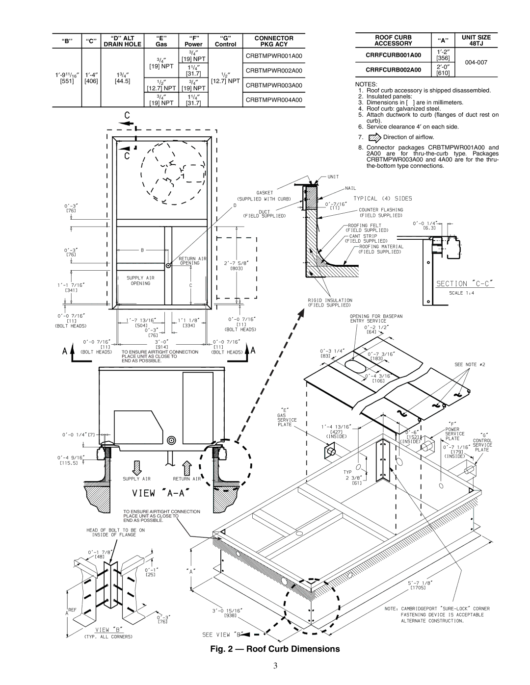
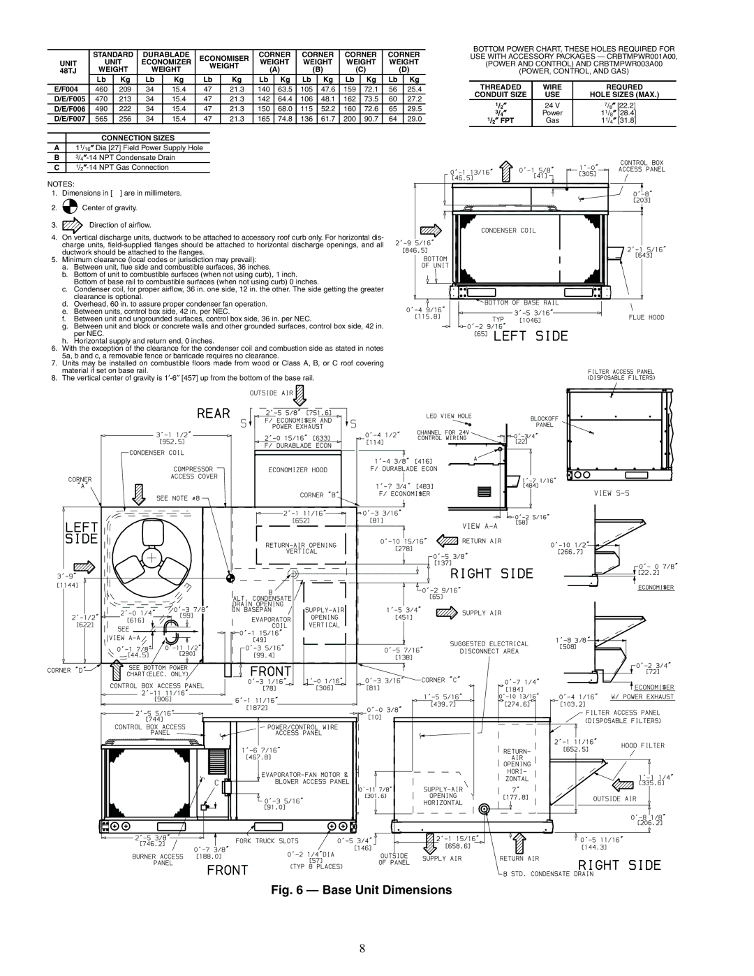
POSITIONING — Maintain clearance around and above unit to provide minimum distance from combustible materials, proper airflow, and service access. See Fig. 6. A properly posi- tioned unit will have the following clearances between unit and roof curb: 1/4-in. clearance between roof curb and base rails on each side and duct end of unit; 1/4-in. clearance between roof curb and condenser coil end of unit. (See Fig. 2, section C-C.)

Do not install unit in an indoor location. Do not locate unit air inlets within 10 ft of exhaust vents or other sources of con- taminated air or as local codes require.

Be sure that unit is installed so that snow will not block the combustion intake or flue outlet.

Unit may be installed directly on wood flooring or on Class A, B, or C roof-covering material when roof curb is used.

Although unit is weatherproof, guard against water from higher level runoff and overhangs.

Flue vent discharge must have a minimum horizontal clear- ance of 4 ft from electric and gas meters, gas regulators, and gas relief equipment.

Minimum distance between unit and other electrically live parts is 48 inches.

Flue gas can deteriorate building materials. Orient unit such that flue gas will not affect building materials.

Adequate combustion-air space must be provided for proper operation of this equipment. Be sure that installation complies with all local codes and Section 5.3, Air for Combustion and Ventilation, NFGC (National Fuel Gas Code), and ANSI (American National Standards Institute) Z223.1, and NFPA (National Fire Protection Association) 54 TIA-54-84-1. In Canada, installation must be in accordance with the CAN1- B149 installation codes for gas burning appliances.

After unit is in position, remove rigging skids and shipping materials.

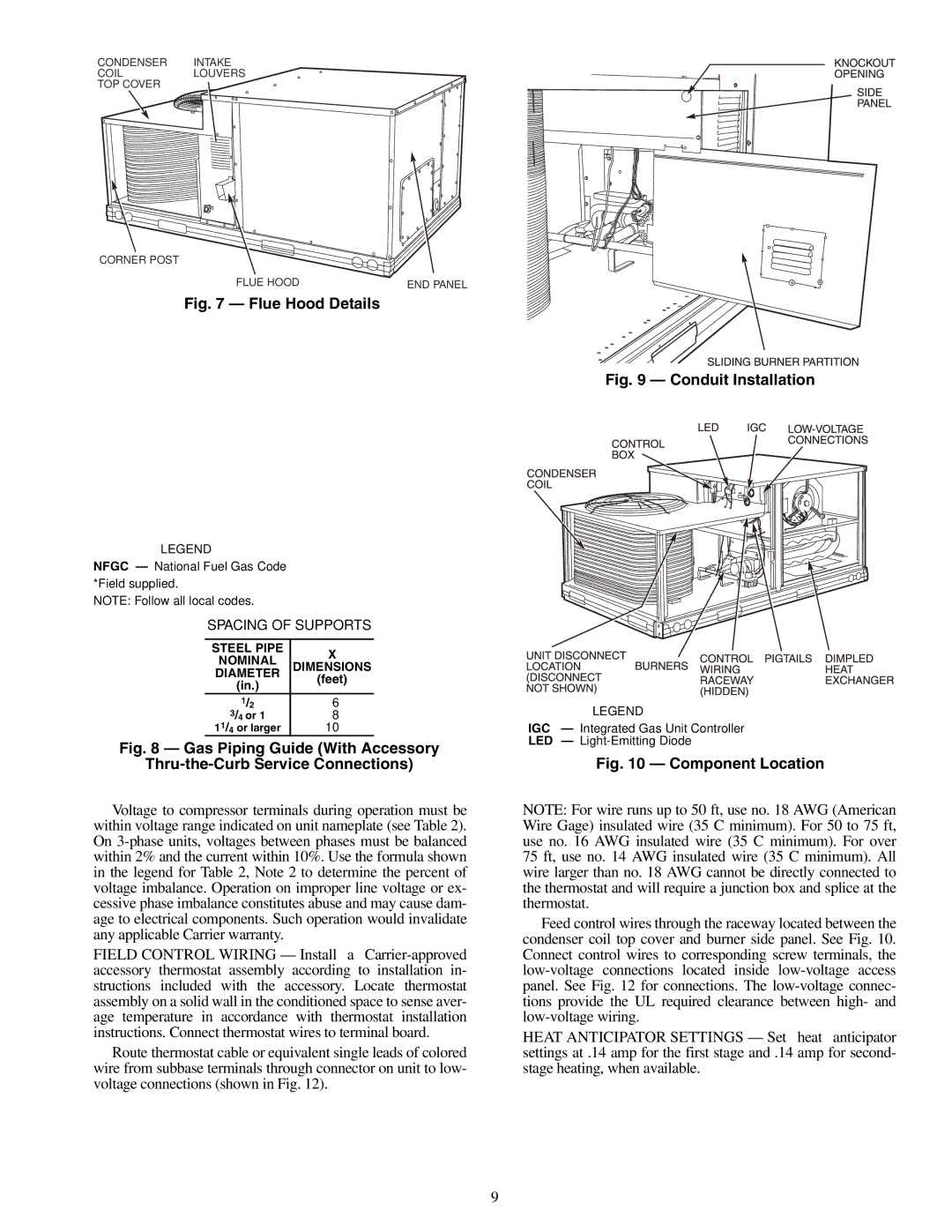
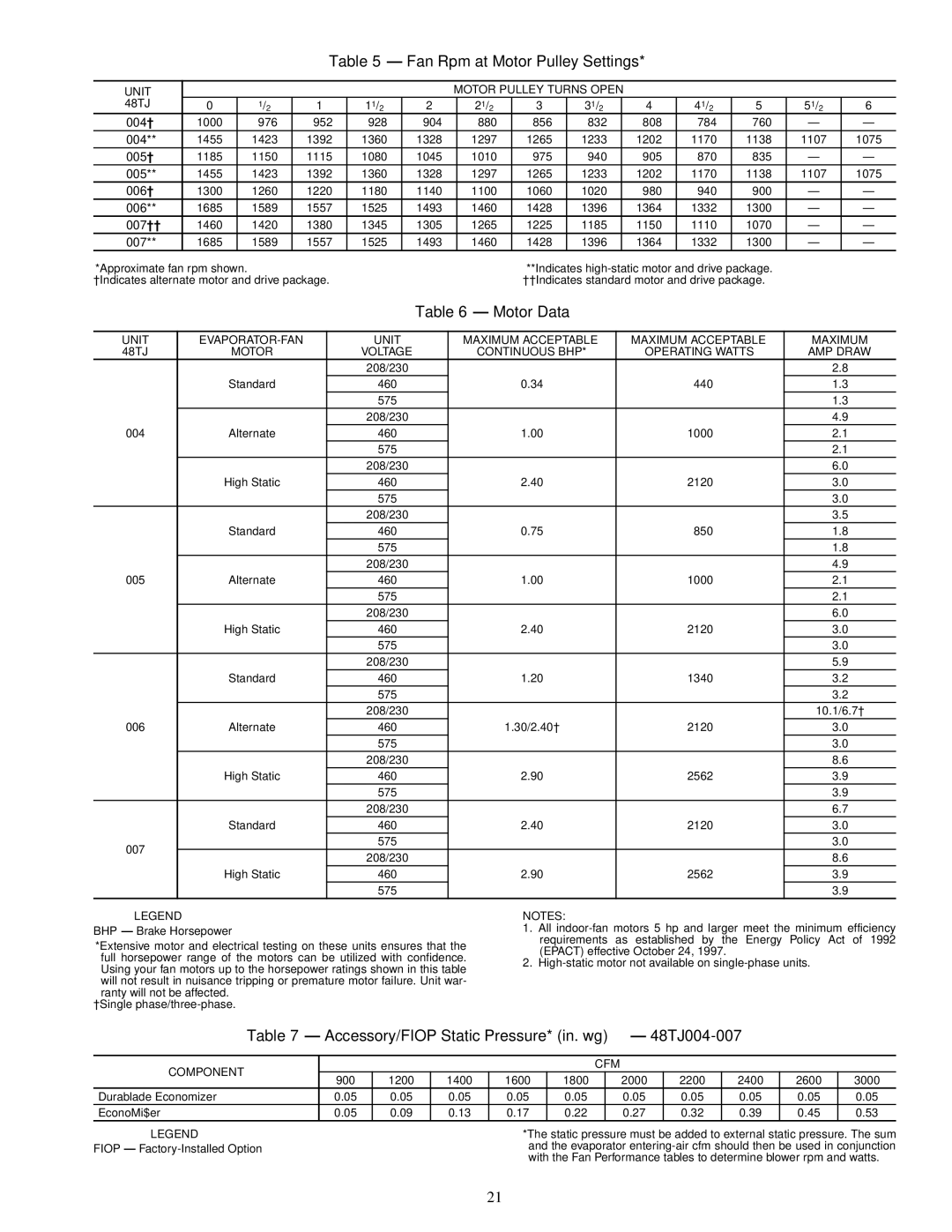
Step 5 — Install Flue Hood — Flue hood is shipped screwed to the burner compartment access panel. Remove from shipping location and using screws provided, install flue hood and screen in location shown in Fig. 7.

For units size 004-006 being installed in California Air Quality Management Districts, which require NOx emissions of 40 nanograms/joule or less, a field-installed low NOx kit must be used.

Step 6 — Install Gas Piping — Unit is equipped for use with type of gas shown on nameplate. Refer to local build- ing codes, or in the absence of local codes, to ANSI Z223.1 en- titled National Fuel Gas Code. In Canada, installation must be in accordance with the CAN1.B149.1 and CAN1.B149.2 in- stallation codes for gas burning appliances.

For natural gas applications, gas pressure at unit gas connection must not be less than 4 in. wg or greater than

13.0in. wg while unit is operating. On 48TJ005,006,007 high heat units, the gas pressure at unit gas connection must not be less than 5 in. wg or greater than 13 in. wg while the unit is operating. For propane applications, the gas pressure must not be less than 5 in. wg or greater than 13 in. wg at the unit connection.

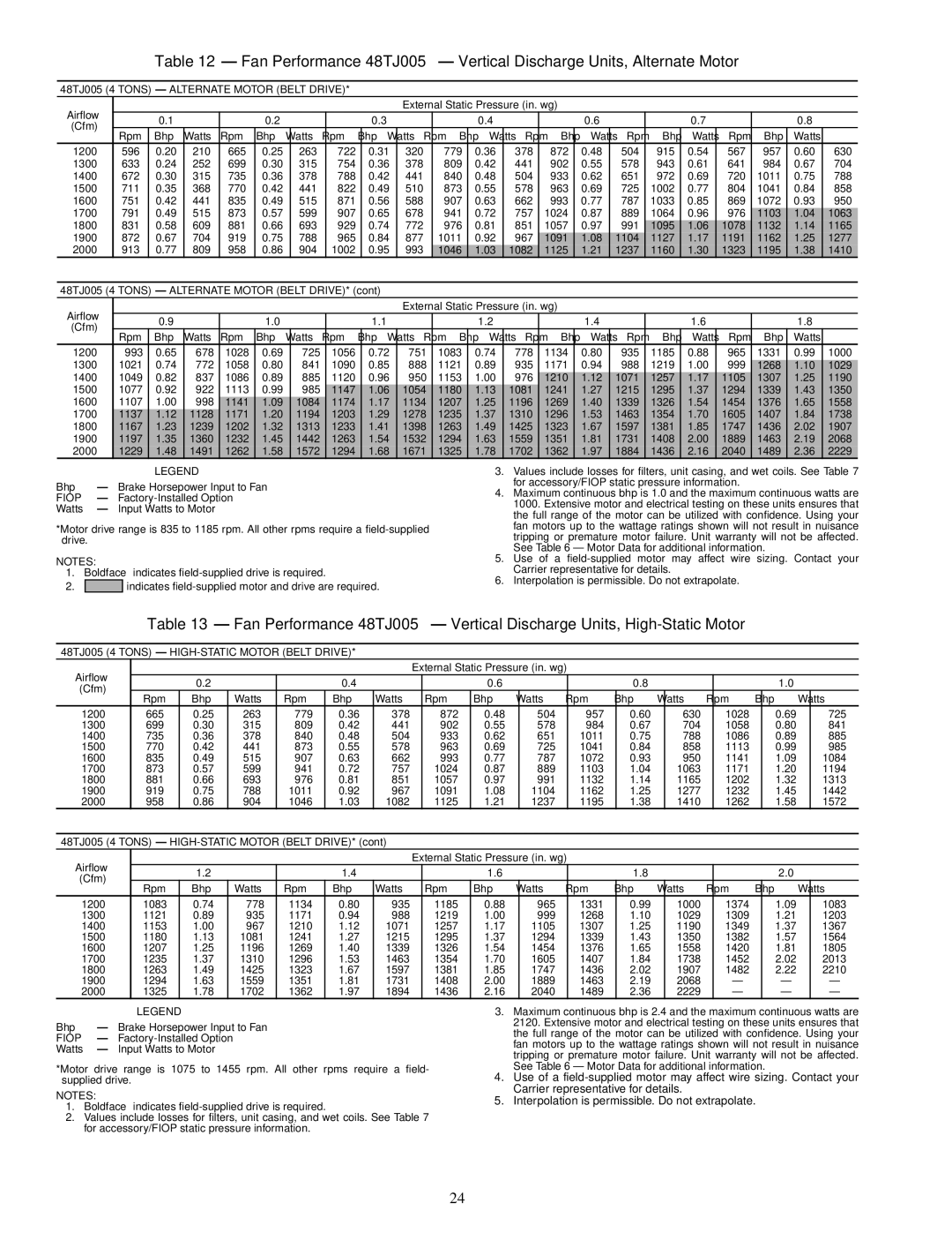
Size gas sully piping for 0.5 in. wg maximum pressure drop. Do not use supply pipe small than unit gas connection. Support gas piping as shown in the table in Fig. 8. For example, a 3/4-in. gas pipe must have one field-fabricated support beam every 8 ft. Therefore, an 18-ft long gas pipe would have a minimum of 2 support beams, a 48-ft long pipe would have a minimum of 6 support beams.

See Fig. 8 for typical pipe guide and locations of external manual main shutoff valve.

4
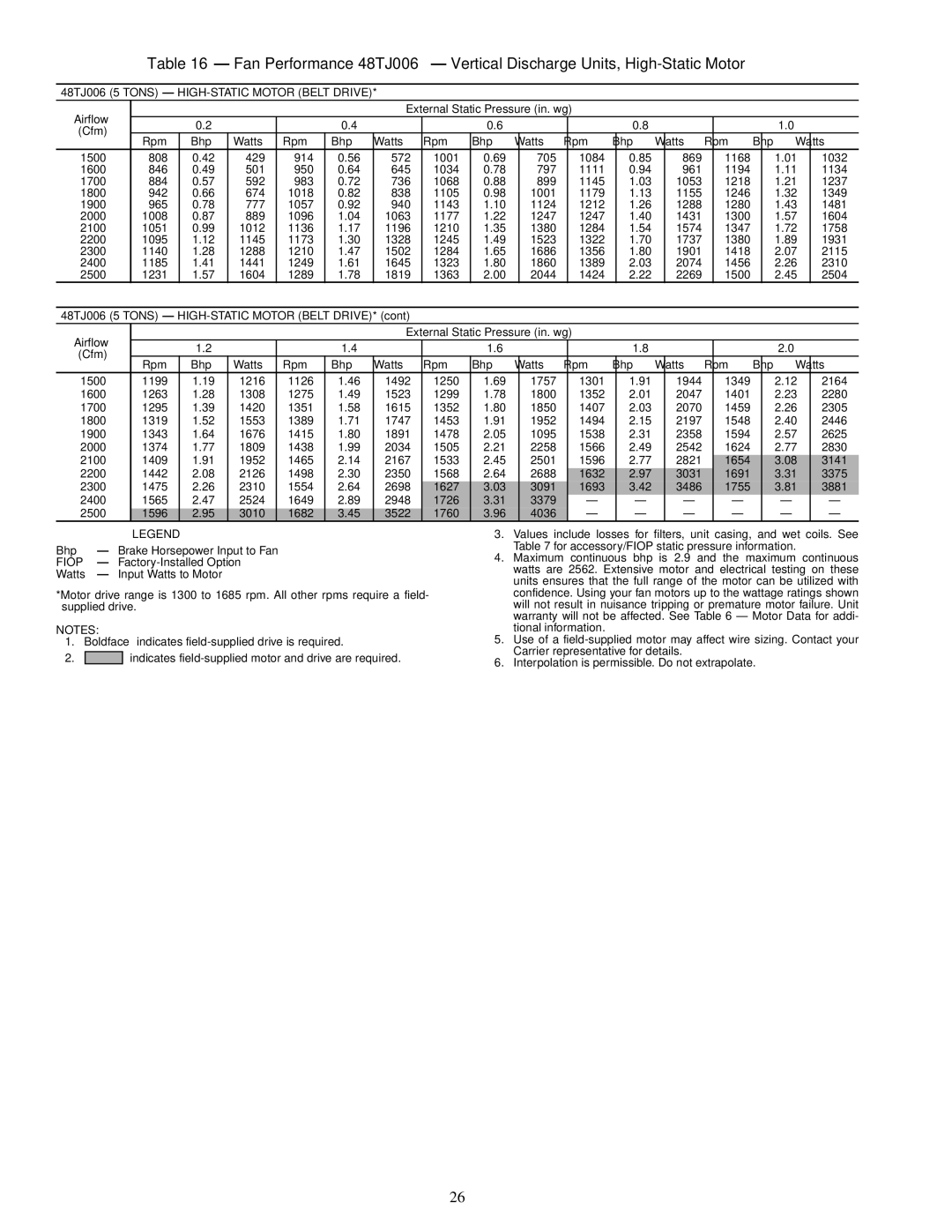
Image 4
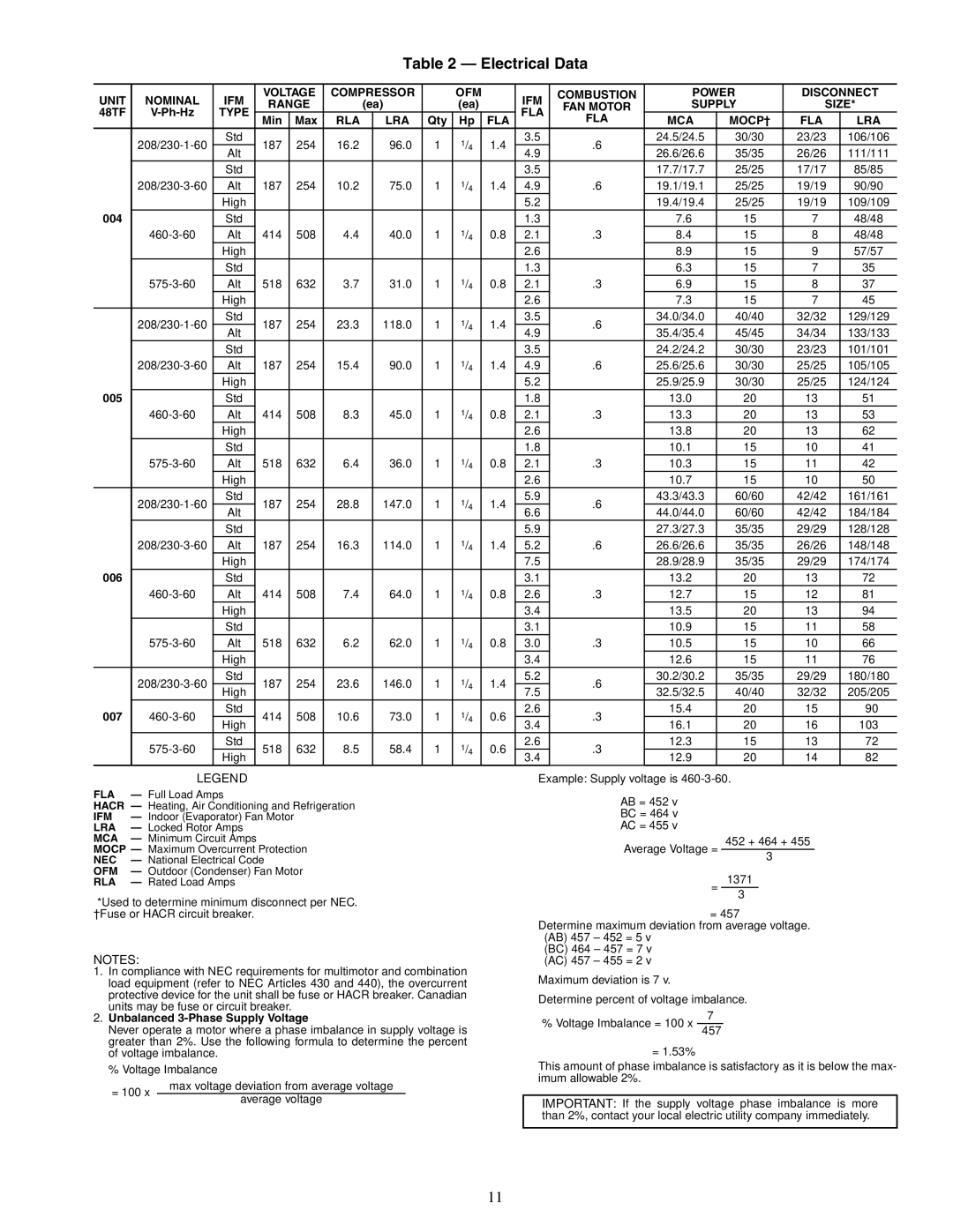
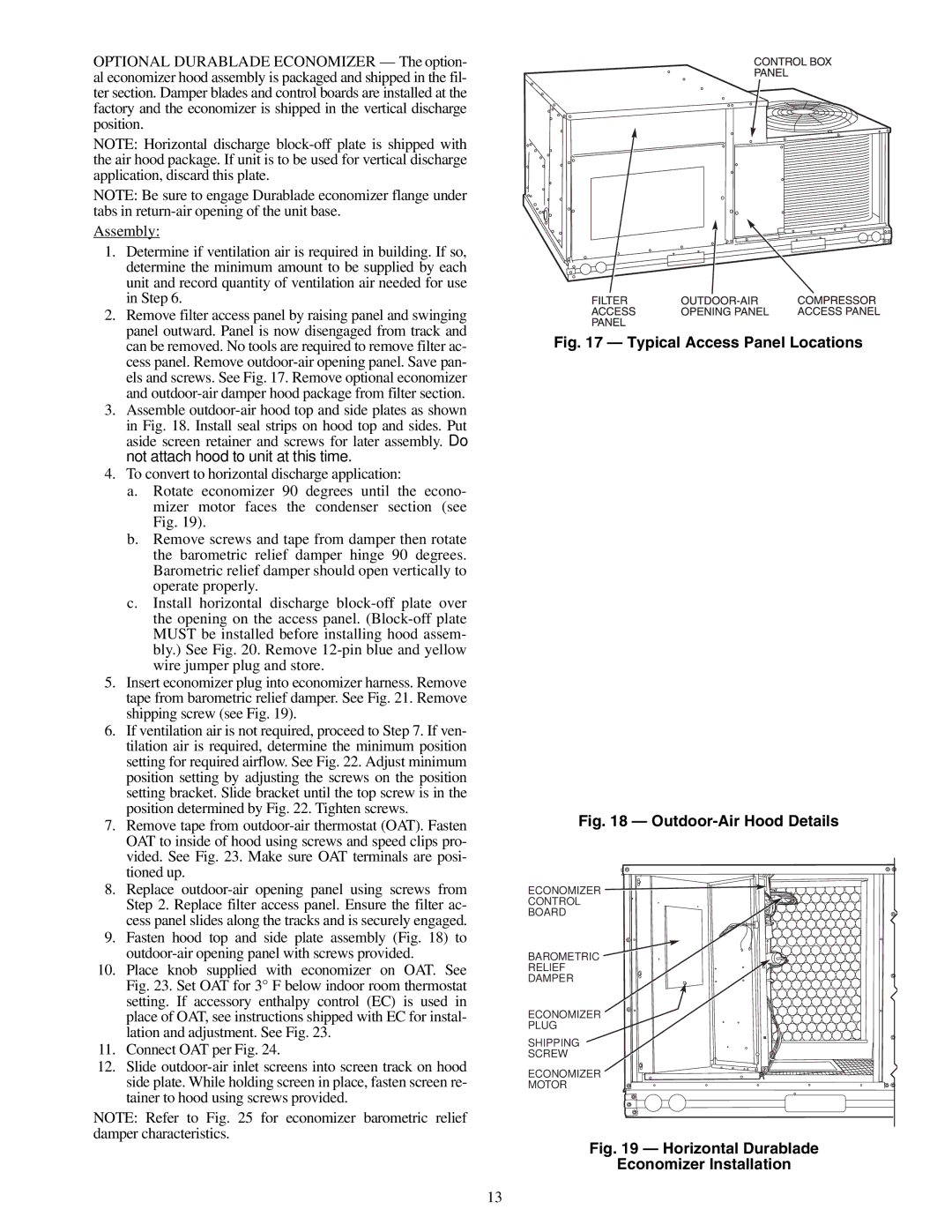
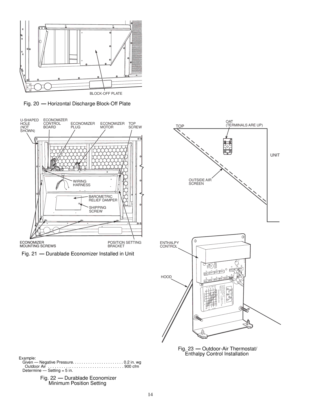
Contents Installation, Start-Up Service Instructions Horizontal Conversion Panels Viewed from Duct End Roof Curb Dimensions Unit Leveling Tolerances Make Electrical Connections Physical Data Unit Size 48TJLOSS-OF-CHARGE LOW Pressure Base Unit Dimensions Conduit Installation Flue Hood DetailsPower Wiring Connections Electrical Data Supply SizeType FLA RLA LRAMake Outdoor-Air Adjustments and Install Outdoor-Air Hood Typical Access Panel Locations Enthalpy Control Installation Horizontal Discharge Block-Off PlateWiring Connections for Outdoor-Air Thermostat Outdoor-Air Hood Assembly EconoMi$er Wiring Wiring Diagram for Power Exhaust System Default Potentiometer Settings Changeover Set PointsBelt Drive Motor Mounting Accessory/FIOP Static Pressure* in. wg 48TJ004-007 Fan Rpm at Motor Pulley SettingsMotor Data 48TJ004 3 Tons Standard Motor Direct Drive 48TJ004 3 Tons Alternate Motor Belt Drive48TJ004 3 Tons HIGH-STATIC Motor Belt Drive 48TJ005 4 Tons Standard Motor Direct Drive48TJ005 4 Tons Alternate Motor Belt Drive 48TJ006 5 Tons Standard Motor Direct Drive 48TJ006 5 Tons Alternate Motor Belt Drive48TJ006 5 Tons HIGH-STATIC Motor Belt Drive 48TJ007 6 Tons Standard Motor Belt Drive 48TJ007 6 Tons HIGH-STATIC Motor Belt Drive 109 149189 2291028 10641005 93848TJ005 4 Tons Alternate Motor Belt Drive 8171700 750 473 806 536 1900 826 63048TJ005 4 Tons HIGH-STATIC Motor Belt Drive 1600 770 420 826 483 1700 811 494 865 5671800 852 578 1900 894 5671221 1600 826 483 931 641 1020 788 1101 956 11781252 1700 865 567 966 725 1051 883 1133 1061 1205885 623 942 700 928 700 982 779971 787 1022 867 1015 891 1063 9981900 982 779 1084 932 1160 1006 1223 1114 2000 1022 867 1121 1014 1188 1097 1254 12162100 1063 998 1140 1064 1196 1272 1292 2200 1104 1081 1159 1106 1229 1258Elevation Altitude CompensationGas Propane Orifice Size† 000 Heating Page Service Lubrication Cooling Charging Chart, 48TJ004 Flash† LED Error Code DescriptionFlashes Burner Tray Details LED Error Code Service Analysis Heating Service AnalysisSymptom Cause Remedy Problem Cause RemedyCooling Service Analysis Compressor operates continuouslyDurablade Economizer Troubleshooting Damper does notEconoMi$er Troubleshooting Problem Potential Cause RemedyTypical Wiring Diagram and Component Arrangement Switch Max. Vent Position SW4Page START-UP Checklist